
OCR Specification focus:
‘Electrical power: P = VI, P = I²R, and P = V²/R.’
Understanding power in electrical circuits is fundamental to analysing how energy is transferred and used by electrical devices. These relationships link voltage (potential difference), current, and resistance to the rate of energy transfer, forming the basis of practical circuit design and performance evaluation.
The Concept of Power in Electrical Circuits
Electrical power describes the rate at which energy is transferred or converted in a circuit. In physics, this refers to how quickly electrical energy is converted into other forms such as light, heat, or mechanical energy.
Power (P): The rate of energy transfer or conversion in a circuit, measured in watts (W), where 1 W = 1 joule per second (J s⁻¹).
Power is not a stored quantity but a measure of energy transfer per unit time, indicating how “fast” electrical energy is being used or produced.
The Fundamental Power Equation: P = VI
The most direct relationship between power, voltage, and current is given by:
EQUATION
—-----------------------------------------------------------------
Electrical Power (P) = Voltage (V) × Current (I)
P = VI
P = electrical power (watts, W)
V = potential difference (volts, V)
I = current (amperes, A)
—-----------------------------------------------------------------
This relationship stems from the definitions of energy and charge:
Since energy transferred W=VQW = VQW=VQ and current I=Q/tI = Q/tI=Q/t, substituting these gives P=W/t=VQ/t=VIP = W/t = VQ/t = VIP=W/t=VQ/t=VI.
Thus, power depends directly on both the potential difference across a component and the current through it.
When a current flows through a resistor or device, electrical energy is transferred to that component at a rate determined by the product of V and I.

Simple DC circuit showing a source driving current through a single resistor in a closed loop. This is the canonical context for the power relations P=VIP = VIP=VI, P=I2RP = I^2RP=I2R, and P=V2/RP = V^2/RP=V2/R. The visual intentionally omits non-essential parts to keep focus on power in resistive components. Source.
Deriving Alternative Power Equations
The fundamental relationship P=VIP = VIP=VI can be combined with Ohm’s Law, V=IRV = IRV=IR, to yield two useful variants. These are essential for circuit analysis when certain quantities are known but others are not.
Power in Terms of Current and Resistance: P = I²R
By substituting V=IRV = IRV=IR into P=VIP = VIP=VI:
EQUATION
—-----------------------------------------------------------------
Power in Resistive Form (P) = Current² (I²) × Resistance (R)
P = I²R
I = current (amperes, A)
R = resistance (ohms, Ω)
—-----------------------------------------------------------------
This version expresses power in terms of current and resistance only. It is particularly useful for resistive components such as filament lamps or heating elements, where the current is the main known variable.
The squared relationship shows that doubling the current quadruples the power dissipated in the resistor, making it vital to consider current ratings to avoid overheating or damage.
Power in Terms of Voltage and Resistance: P = V²/R
Alternatively, substituting I=V/RI = V/RI=V/R into P=VIP = VIP=VI gives another useful expression:
EQUATION
—-----------------------------------------------------------------
Power in Voltage Form (P) = Voltage² (V²) ÷ Resistance (R)
P = V²/R
V = potential difference (volts, V)
R = resistance (ohms, Ω)
—-----------------------------------------------------------------
This version relates power to the voltage across a component and its resistance. It is especially valuable when a circuit’s voltage is fixed (for example, in mains circuits or power supplies), allowing calculation of the energy transfer rate without knowing the current explicitly.
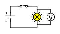
A simple circuit with a voltmeter (V) connected in parallel across the component. Correct placement ensures the measured potential difference corresponds to the device’s terminals for use in P=VIP = VIP=VI or P=V2/RP = V^{2}/RP=V2/R. The diagram is deliberately minimal and does not include an ammeter to avoid clutter. Source.
Understanding Power Dissipation
In resistive components, electrical energy is converted into thermal energy due to collisions between free electrons and atoms in the conductor. This process is known as power dissipation.

Close-up photograph of a tungsten filament glowing inside a halogen lamp, illustrating electrical power converted to heat and light. This real-world visual exemplifies resistive (Joule) heating consistent with P=I2RP = I^2RP=I2R. Extra detail note: the image shows a halogen lamp enclosure, which is beyond the syllabus scope but does not add conceptual complexity. Source.
Key points about power dissipation:
It is unavoidable in conductors and resistors when current flows.
The rate of heating is directly proportional to I2RI²RI2R.
Lower resistance or reduced current can minimise wasted energy, improving efficiency.
Materials with low resistivity, such as copper, are chosen for power cables to reduce unwanted heating.
Direction of Energy Transfer
In electrical circuits:
Power supplied by a source (e.g. a battery or cell) is positive, representing energy delivered to the circuit.
Power dissipated in resistors or devices is negative, representing energy lost from the electrical system as heat or other forms.
For a complete circuit, the total power supplied equals the total power dissipated, ensuring energy conservation. This aligns with the principle that energy can neither be created nor destroyed, only transformed.
Power Ratings and Device Safety
Every electrical device is designed to operate safely within a specific power rating — the maximum rate of energy transfer it can handle without damage.
Exceeding the rated power causes excessive heating and potential failure.
Fuses and circuit breakers act as protective components that disconnect the circuit when power exceeds safe limits.
Manufacturers label devices with voltage and power ratings (e.g. “230 V, 60 W”) so users can determine the expected current draw using I=P/VI = P/VI=P/V.
Understanding and applying the power equations helps ensure that circuits are designed for safe and efficient energy transfer.
Energy Transfer and Power Efficiency
The concept of efficiency links power to useful energy conversion.
A device’s useful power output divided by its total power input gives its efficiency fraction.
Although efficiency is treated in a separate subsubtopic, it is conceptually tied to the power equations discussed here because losses due to resistance and heating directly reduce the useful output of electrical systems.
Summary of Relationships
To apply the power equations effectively, students should memorise the following key relationships and when to use them:
P=VIP = VIP=VI: Use when both voltage and current are known.
P=I2RP = I²RP=I2R: Use when current and resistance are known.
P=V2/RP = V²/RP=V2/R: Use when voltage and resistance are known.
These equations form the foundation for analysing energy transfer, electrical efficiency, and circuit design in both theoretical and experimental contexts.
Practice Questions
Question 1 (2 marks)
A resistor has a potential difference of 6.0 V across it and a current of 0.50 A flowing through it.
Calculate the electrical power dissipated by the resistor. State the equation you use.
Mark scheme:
1 mark for correct equation: P = VI
1 mark for correct substitution and answer: P = 6.0 × 0.50 = 3.0 W
Question 2 (5 marks)
A filament lamp is connected to a 12 V battery. When the lamp is operating normally, it draws a current of 0.40 A.
(a) Calculate the power dissipated by the lamp. (2 marks)
(b) The lamp’s resistance increases as its temperature rises. Explain, using the appropriate power equations, how this affects the current and power output of the lamp once it reaches operating temperature. (3 marks)
Mark scheme:
(a)
1 mark for correct equation: P = VI
1 mark for correct substitution and answer: P = 12 × 0.40 = 4.8 W
(b)
1 mark for recognising that resistance increases with temperature.
1 mark for linking increased resistance to a reduced current (from I = V/R).
1 mark for correctly stating that power output will stabilise or decrease because P = I²R or P = V²/R and current falls as resistance rises.
FAQ
If the resistance doubles and the voltage remains constant, the current halves (since I = V/R).
Substituting into P = VI gives P = V(V/R) = V²/R.
Because R has doubled, the power output becomes half its original value. This means less energy is transferred per second, and the component will operate at a lower power level or brightness if it is a lamp.
Each form of the power equation is convenient depending on which quantities are known:
P = VI is general and applies to all situations.
P = I²R is useful when current and resistance are known.
P = V²/R is ideal when voltage and resistance are known.
Using the correct form simplifies calculations and avoids introducing unnecessary steps, especially during experiments where only certain variables can be measured accurately.
In AC circuits, current and voltage continuously vary with time. The average power is found using root mean square (rms) values of current and voltage.
The same relationships apply — P = VI, P = I²R, and P = V²/R — but all quantities must use rms values rather than peak values.
This ensures that calculated power represents the equivalent constant DC power producing the same heating effect in a resistor.
Larger resistors can safely dissipate more energy as heat. When electrical power (P = I²R) increases, the component must release that energy without overheating.
Physical size allows for:
Greater surface area for heat dissipation.
Materials with higher thermal tolerance.
Lower temperature rise for the same power.
This ensures that the resistor operates safely and reliably under sustained current flow.
When current flows through transmission cables, resistance causes heating losses described by P = I²R.
To minimise these losses:
Power companies transmit electricity at high voltage and low current, keeping I²R small.
Transformers step up voltage for transmission and step it down again for safe domestic use.
Reducing current through this method dramatically cuts wasted energy and improves efficiency in national power grids.
