
OCR Specification focus:
‘For parallel resistors, 1/R = 1/R₁ + 1/R₂ + … .’
Understanding the total resistance in parallel circuits is essential for analysing complex electrical systems, where multiple pathways for current affect how potential difference and resistance interact across components.
Total Resistance in Parallel Circuits
In a parallel circuit, components are connected so that each resistor or device has the same potential difference across it. The current from the supply splits between the available paths according to each component’s resistance. The total resistance of the circuit therefore determines how much current the source must provide overall. This concept forms a vital part of circuit analysis and practical applications such as household wiring, electrical distribution systems, and electronic devices.
Understanding the Parallel Arrangement
In parallel circuits, each resistor is connected directly across the same two points, forming branches. This means:
The potential difference (p.d.) across each resistor is identical to the supply voltage.
The total current from the source equals the sum of the currents in all branches.
Adding more branches provides additional pathways for current, reducing the total resistance.
This configuration contrasts with series circuits, where current is the same through each resistor but potential differences add.
Kirchhoff’s Laws and Parallel Circuits
The behaviour of currents and potential differences in parallel networks follows Kirchhoff’s first law (the current law), which states that the total current entering a junction equals the total current leaving it. This principle underpins the mathematical relationship for total resistance in parallel.

Annotated diagram illustrating Kirchhoff’s Current Law, showing currents entering and leaving a junction. It visualises charge conservation in a parallel network and supports understanding of current distribution and the total current rule. Source.
Each branch obeys Ohm’s law, V = IR, with the same voltage (V) but differing currents (I) depending on resistance (R). Summing these currents provides the key relationship between total current and total resistance.
Deriving the Formula for Total Resistance in Parallel
When two or more resistors are connected in parallel, the reciprocal of the total resistance equals the sum of the reciprocals of each individual resistance.

Diagram of resistors in parallel, each connected across the same two points. The voltage is identical across all branches while current varies. This visualises the reciprocal relationship used to calculate total resistance. Source.
EQUATION
—-----------------------------------------------------------------
Total Resistance in Parallel (R) = 1 / (1/R₁ + 1/R₂ + …)
R = Total resistance of the circuit (ohms, Ω)
R₁, R₂, … = Individual resistances of parallel components (ohms, Ω)
—-----------------------------------------------------------------
Between any two nodes of the parallel network, the voltage remains constant, while the total current increases with the number of paths. As a result, the total resistance always becomes smaller than the smallest individual resistor.
The Concept of Current Division
Because the voltage across each branch is identical, the current through each resistor depends on its resistance. Lower resistance branches carry proportionally higher current. This distribution of current is known as current division.
A resistor with half the resistance of another will carry twice the current, assuming both are in parallel.
The total current equals the sum of branch currents, reinforcing Kirchhoff’s first law.
Simplifying Networks of Parallel Resistors
To analyse a circuit with multiple resistors in parallel:
Identify all resistors connected between the same two points.
Apply the reciprocal formula to find 1/R_total.
Invert the result to find R_total.
Replace these resistors with a single equivalent resistor in further calculations.
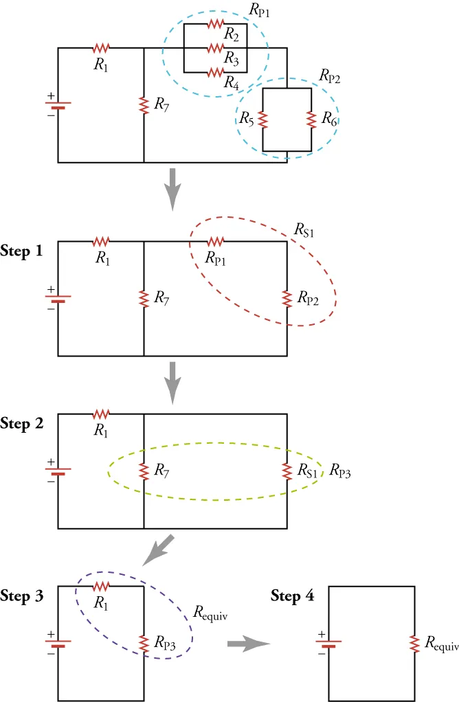
A sequential reduction diagram showing how parallel groups are replaced by an equivalent resistor. It clarifies the practical process of simplifying complex resistor networks. The figure also includes series steps, shown for context beyond this subtopic. Source.
This stepwise simplification is frequently used alongside series combinations to handle mixed component circuits later in the syllabus.
Two-Resistor Special Case
For two resistors only, the formula simplifies to a specific relationship that is especially useful:
EQUATION
—-----------------------------------------------------------------
Total Resistance for Two Parallel Resistors (R) = (R₁ × R₂) / (R₁ + R₂)
R₁, R₂ = Individual resistances (ohms, Ω)
—-----------------------------------------------------------------
This simplified version provides a quick way to determine equivalent resistance without calculating reciprocals separately. It reveals that the effective resistance is dominated by the smaller resistor, as the current preferentially flows through the path of least resistance.
Physical Interpretation and Energy Considerations
In practical terms, when more resistors are added in parallel, the circuit draws more current from the supply for the same voltage. This increases power consumption, given by P = VI, where V remains constant and I increases. Therefore, parallel connections enhance the system’s capability to deliver higher total current while maintaining the same potential difference across all loads.
Common Applications of Parallel Circuits
Parallel configurations are fundamental in electrical and electronic systems because they ensure each component receives the same supply voltage. Typical examples include:
Household wiring, where appliances operate independently at a constant supply voltage.
Lighting circuits, allowing bulbs to remain lit even if one fails.
Electronic boards, where sensors and resistors function with uniform p.d. but variable current.
These examples underline the importance of parallel networks in practical electrical engineering and domestic systems.
Measurement and Verification
In laboratory conditions, verifying the relationship between total and individual resistances in parallel involves measuring current and potential difference:
Use a voltmeter connected across the resistors to confirm equal potential difference.
Use ammeters in each branch and in the main line to confirm that the total current equals the sum of branch currents.
Calculate total resistance by dividing the supply voltage by the total current, comparing with the theoretical formula.
Such experiments provide tangible evidence of Kirchhoff’s current law and reinforce the predictive accuracy of the reciprocal resistance equation.
Key Characteristics of Parallel Circuits
The total resistance is always less than any single resistor in the network.
Adding more resistors decreases total resistance further.
Each resistor shares the same voltage, simplifying potential difference analysis.
The total current is divided among branches according to their resistances.
Parallel arrangements improve reliability, since one component failing does not interrupt others.
Understanding these properties ensures accurate circuit design and safe, efficient operation across electrical and electronic systems.
Practice Questions
Question 1 (2 marks)
Two resistors of 6.0 Ω and 3.0 Ω are connected in parallel across a 12 V supply.
(a) Calculate the total resistance of the parallel combination.
(b) State why the total resistance is less than the smallest individual resistance.
Mark Scheme:
(a)
• Correct use of parallel resistance formula: 1/R = 1/6 + 1/3 (1 mark)
• Correct answer: R = 2.0 Ω (1 mark)
(b)
• Because adding parallel branches increases total current for the same potential difference, hence total resistance decreases (1 mark)
Question 2 (5 marks)
A circuit consists of a 9.0 V battery connected to three resistors: a 4.0 Ω resistor in series with two resistors of 6.0 Ω and 3.0 Ω connected in parallel.
(a) Calculate the total resistance of the circuit.
(b) Determine the total current supplied by the battery.
(c) Calculate the current through each resistor in the parallel branch.
(d) Explain how the current division in the parallel branch illustrates Kirchhoff’s first law.
Mark Scheme:
(a)
• Correct use of parallel formula: 1/R_parallel = 1/6 + 1/3 (1 mark)
• Correct parallel result: R_parallel = 2.0 Ω (1 mark)
• Correct total resistance: R_total = 4.0 + 2.0 = 6.0 Ω (1 mark)
(b)
• Correct calculation: I_total = 9.0 / 6.0 = 1.5 A (1 mark)
(c)
• Voltage across parallel branch = 9.0 − (1.5 × 4.0) = 3.0 V (1 mark)
• Current in 6.0 Ω branch = 3.0 / 6.0 = 0.50 A (1 mark)
• Current in 3.0 Ω branch = 3.0 / 3.0 = 1.0 A (1 mark)
(d)
• States that total current into the junction (1.5 A) equals the sum of currents through the parallel branches (1.5 A = 0.50 + 1.0) (1 mark)
• References Kirchhoff’s first law: current entering equals current leaving a junction (1 mark)
Total: 5 marks (maximum 5 awarded — any correct numerical or descriptive justification accepted with appropriate working).
FAQ
Adding another resistor in parallel provides an additional path for current to flow. This increases the total current drawn from the supply while the potential difference remains constant.
Since resistance is a measure of opposition to current, more current for the same voltage means the total resistance must be lower. The effect is more pronounced when the added resistor has a small resistance value.
If one resistor has a resistance value much smaller than all the others, it dominates the current flow.
In this case, the total resistance of the parallel combination will be only slightly greater than that smallest resistor’s value.
For example:
A 1 Ω resistor in parallel with a 100 Ω resistor gives a total resistance of about 0.99 Ω.
The current therefore flows mostly through the lower resistance path.
When identical resistors are connected in parallel, the total current divides equally among all branches because each branch has the same resistance and potential difference.
For example:
Two 10 Ω resistors in parallel will each carry half of the total current.
If three are used, each branch carries one-third of the total current.
This is a useful way to share electrical load evenly between components.
Small uncertainties in voltage or current readings can produce larger percentage errors when calculating total resistance, since the reciprocal formula amplifies differences.
To reduce uncertainty:
Use low-resistance ammeters and high-resistance voltmeters to minimise circuit disturbance.
Take multiple readings and calculate mean values.
Keep wire resistances negligible by using short, thick connecting leads.
Accurate measurement ensures calculated resistance aligns closely with theoretical predictions.
Parallel wiring ensures every appliance receives the same potential difference from the mains supply, allowing each to operate independently.
If appliances were connected in series:
The voltage would divide between them, altering performance.
Switching off one device would interrupt the current to all others.
Parallel circuits therefore maintain consistent operation, provide safety advantages, and enable independent control of each electrical load.
