
OCR Specification focus:
‘Analyse circuits with more than one e.m.f. source using Kirchhoff’s laws.’
Circuits with multiple sources of electromotive force (e.m.f.) are common in complex electrical systems. Understanding their analysis using Kirchhoff’s laws is crucial for precise design and troubleshooting.
Multiple Sources of e.m.f.
In many practical circuits, more than one e.m.f. source (such as batteries, cells, or power supplies) may be connected. These sources can either assist or oppose each other depending on their relative orientation and polarity. The analysis of such circuits requires careful application of Kirchhoff’s first law (the junction rule) and Kirchhoff’s second law (the loop rule), ensuring both charge and energy conservation are satisfied.
Kirchhoff’s Laws Overview
Kirchhoff’s First Law: The sum of currents entering a junction equals the sum of currents leaving it — representing the conservation of charge.
This law ensures that electric charge does not accumulate at any point within a circuit. It is applied at nodes where three or more conductors meet.
Kirchhoff’s Second Law: The sum of the electromotive forces (e.m.f.s) around any closed loop equals the sum of the potential drops across the resistive components in that loop.
This second law is an expression of the principle of energy conservation, stating that the energy gained by charges from sources equals the energy lost in resistors and other components within the loop.
Combining e.m.f. Sources
When multiple sources of e.m.f. are present, they may be connected in series or in parallel, and the resulting total e.m.f. depends on their arrangement and relative polarity.
Series e.m.f. Sources
When sources are connected in series:
Their e.m.f.s add if the sources are oriented in the same direction.
Their e.m.f.s subtract if one is reversed relative to the other.
EQUATION
—-----------------------------------------------------------------
Total e.m.f. (E_total) = E₁ ± E₂ ± E₃ …
E = Electromotive force, measured in volts (V)
—-----------------------------------------------------------------
The net e.m.f. determines the direction and magnitude of the current through the circuit, considering the total resistance.
Parallel e.m.f. Sources
When e.m.f. sources are connected in parallel:
They must ideally have identical e.m.f. values to prevent internal currents flowing between them.
If their e.m.f.s differ, circulating currents occur, resulting in internal energy losses and possible heating effects.
In practical applications, parallel sources are used to increase current capacity while maintaining the same voltage. Batteries in large systems often use this configuration to provide stable power with lower internal resistance.
Applying Kirchhoff’s Laws to Multiple Source Circuits
To analyse such circuits systematically:
Assign Current Directions
Assume current directions through each branch; incorrect assumptions only result in negative current values after calculation.
Identify Junctions
Apply Kirchhoff’s first law at each junction to relate the branch currents.
Select Independent Loops
Apply Kirchhoff’s second law around each loop, accounting for all e.m.f. sources and potential drops.
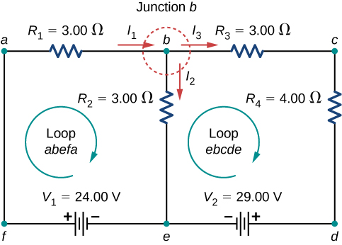
Two-loop circuit with sources V₁ and V₂ in different branches and shared resistors. It illustrates choosing independent loops and writing one KVL equation per loop, together with KCL at the junctions. Values are included only to make the sign conventions and current directions concrete. Source.
Use Sign Conventions
Traverse loops consistently; e.m.f.s are positive when moving from negative to positive terminal, and potential drops across resistors are negative when following the current direction.
Solve Simultaneous Equations
The resulting system of equations can be solved algebraically to find unknown currents and voltages.
This process ensures that both current distribution and voltage levels in the circuit satisfy conservation principles.
Effective e.m.f. and Internal Resistance
Each source has an internal resistance, which affects how its e.m.f. contributes to the overall circuit. When combining sources:
Series combination: Internal resistances add directly.
Parallel combination: The total internal resistance decreases, following the reciprocal relationship used for parallel resistors.
EQUATION
—-----------------------------------------------------------------
Total Resistance in Parallel (r_total) = 1 / (1/r₁ + 1/r₂ + …)
r = Internal resistance of each source (Ω)
—-----------------------------------------------------------------
In series, the total e.m.f. and resistance can be modelled together:
EQUATION
—-----------------------------------------------------------------
Total Series Source Model: E_total = I (R_total + r_total)
E = Total electromotive force (V)
I = Current (A)
R_total = External resistance (Ω)
r_total = Combined internal resistance (Ω)
—-----------------------------------------------------------------
This allows current and voltage to be calculated accurately for circuits with multiple e.m.f. sources.
Assisting and Opposing Sources
Two e.m.f. sources in the same circuit may assist or oppose each other.
Assisting sources provide current in the same direction, reinforcing the total e.m.f.
Opposing sources drive current in opposite directions, reducing the net e.m.f.
For instance, in a loop with two batteries connected in opposition, the effective e.m.f. is the difference between them. If one source is stronger, current flows according to the direction of the greater e.m.f.
Kirchhoff’s Loop Equations with Multiple e.m.f.s
When multiple sources are included in a loop, Kirchhoff’s second law can be written as:
EQUATION
—-----------------------------------------------------------------
ΣE = Σ(IR)
ΣE = Algebraic sum of electromotive forces (V)
I = Current through each component (A)
R = Resistance of each component (Ω)
—-----------------------------------------------------------------
This equation accounts for every e.m.f. and potential drop around the loop. The algebraic signs depend on the direction chosen for the loop traversal and the orientation of each source.
After applying Kirchhoff’s laws, simultaneous equations often arise that describe the relationship between currents in each branch. These equations can be solved using substitution or matrix methods to obtain all required values.
Practical Implications and Circuit Design
Understanding multiple e.m.f. sources is essential for designing systems such as:
Battery banks in renewable energy storage, where cells are combined for higher voltage or current output.
Power supply redundancy in electronics, where sources are connected to ensure reliability.
Electrical measurement bridges and laboratory circuits requiring precise voltage control.
When combining e.m.f. sources practically:
Ensure all sources are of similar capacity and internal resistance to prevent uneven current distribution.
Consider the direction of polarity carefully during connection to avoid short circuits or reverse charging.
Use Kirchhoff’s laws to verify the expected voltages and currents at key points before constructing the circuit.
When sources are connected in parallel, their e.m.f.s should be equal to avoid circulating currents between sources.
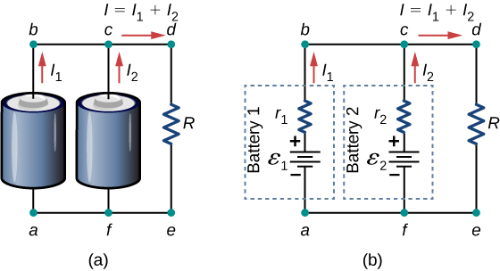
Two real batteries with identical ε are connected in parallel, each modelled with internal resistance. The diagram highlights that the terminal potential difference equals the common source e.m.f. minus the drop across the equivalent internal resistance. Extra detail: the explicit r₁, r₂ labels illustrate internal resistance, which the notes mention when analysing multiple sources. Source.
Common Analytical Insights
A closed loop containing multiple sources requires careful energy accounting — energy supplied by each source equals energy dissipated across all resistive elements.
A junction with currents from multiple sources must obey charge conservation — the total current entering equals the total current leaving.
When solving for unknowns, always maintain consistent loop directions and sign conventions to prevent algebraic errors.
Use a consistent sign convention: traverse from − to + across an e.m.f. → +E; from + to − → −E; across a resistor in current direction → −IR.
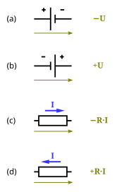
Diagram showing KVL traversal across batteries and resistors with corresponding algebraic signs. It reinforces that potential rises across sources and drops across resistors must sum to zero around any closed loop. The graphic includes only essential labels to avoid visual clutter. Source.
The application of Kirchhoff’s first and second laws thus enables complete analysis of circuits containing multiple sources of e.m.f., ensuring both theoretical accuracy and practical safety in electrical system design.
Practice Questions
Question 1 (2 marks)
Two identical cells, each with an e.m.f. of 1.5 V and internal resistance of 0.2 Ω, are connected in series aiding one another.
Calculate the total e.m.f. of the combination and the total internal resistance.
Mark scheme:
States total e.m.f. = 3.0 V (1 mark)
States total internal resistance = 0.4 Ω (1 mark)
Question 2 (5 marks)
A circuit contains two e.m.f. sources connected in opposition, as shown below.
Battery A has an e.m.f. of 12 V and internal resistance 0.5 Ω.
Battery B has an e.m.f. of 10 V and internal resistance 0.5 Ω.
They are connected in series with an external resistor of 3.0 Ω.
(a) State which battery drives the current in the circuit. (1 mark)
(b) Determine the net e.m.f. acting around the circuit. (1 mark)
(c) Calculate the current in the circuit. (2 marks)
(d) State and explain what would happen if the batteries were connected the other way around, assisting each other instead of opposing. (1 mark)
Mark scheme:
(a) Battery A drives the current (1 mark) — higher e.m.f. means its polarity dominates.
(b) Net e.m.f. = 12 V – 10 V = 2 V (1 mark).
(c) Total resistance = 3.0 + 0.5 + 0.5 = 4.0 Ω; Current I = 2 / 4.0 = 0.5 A (2 marks: 1 for correct total resistance, 1 for correct current).
(d) If the batteries assisted each other, total e.m.f. = 22 V; current increases substantially as both drive current in the same direction (1 mark).
FAQ
When cells with unequal e.m.f.s are connected in parallel, a circulating current flows between them due to the potential difference. This causes internal heating and wastes energy.
The stronger cell drives current through the weaker one, potentially damaging it or discharging it prematurely.
To prevent this:
Only connect cells with the same e.m.f. in parallel.
Ensure similar internal resistances and charge states.
Use current-limiting resistors if unavoidable in practical systems.
Each source’s internal resistance reduces its effective terminal voltage when current flows.
In series, the internal resistances add, increasing total resistance and reducing total current.
In parallel, the combined internal resistance is lower, but if the e.m.f.s differ slightly, internal resistances determine how much current each source contributes. The source with lower internal resistance provides a larger share of the total current.
When multiple e.m.f. sources are present, especially with opposing or mixed orientations, simple resistor addition and voltage division rules no longer apply correctly.
Kirchhoff’s laws allow for:
Proper treatment of loops where sources interact.
Consistent sign conventions for energy gain and loss.
Solving simultaneous equations that describe current flow and potential differences in every branch.
Yes. This occurs when opposing e.m.f.s exactly balance and the sum of potential rises equals the sum of potential drops in the loop.
In this condition:
The net e.m.f. = 0 V.
No current flows in the circuit, although potential differences still exist across internal resistances.
This can happen deliberately in circuits designed for calibration or null measurements, such as potentiometers.
To ensure safety and reliability:
Check all source polarities before connection to avoid reverse charging.
Match e.m.f. and capacity ratings for sources in parallel.
Allow sources to rest between tests to prevent overheating from internal current flow.
Use appropriate connecting leads and fuses for the expected current levels.
These steps prevent excessive current, overheating, and potential cell damage in experimental or practical setups.
