
OCR Specification focus:
‘Terminal potential difference equals e.m.f. minus ‘lost volts’ inside the source.’
In electrical circuits, a power source such as a cell or battery provides electrical energy to a circuit. However, some energy is inevitably lost within the source itself, leading to a difference between the electromotive force (e.m.f.) and the terminal potential difference (terminal p.d.). Understanding this concept is essential for analysing real electrical systems and determining how internal resistance affects circuit performance.
Understanding Terminal Potential Difference and Lost Volts
Electromotive Force (e.m.f.)
The e.m.f. of a source represents the total electrical energy provided by the source per unit charge that passes through it. It is the maximum potential difference the source could deliver when no current is flowing, i.e. in an open circuit.
Electromotive Force (e.m.f.): The energy supplied by a source to each coulomb of charge passing through it, measured in volts (V).
When a circuit is closed and current begins to flow, not all of the e.m.f. is available across the external components. Some energy is used to overcome opposition within the source itself, leading to lost volts.
Internal Resistance and Lost Volts
All practical power sources contain some internal resistance (r) — a resistance within the cell or battery that causes a voltage drop when current flows. This resistance arises due to the materials used inside the cell and chemical limitations in energy transfer.
Internal Resistance: The opposition to current flow within the power source itself, causing energy loss inside the source.
As current flows through this internal resistance, part of the total energy supplied by the source is dissipated as heat. The voltage corresponding to this energy loss is known as the lost volts.
Lost Volts: The potential difference across the internal resistance of a source, representing the energy per coulomb wasted as heat inside the source
This means that the energy available to the external circuit is reduced by the amount lost internally. Therefore, the terminal potential difference (the measurable voltage across the terminals of the cell) is less than the e.m.f. whenever current flows.
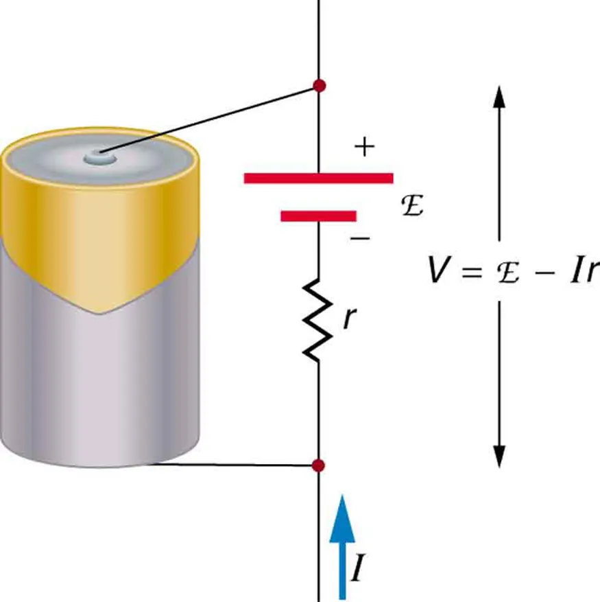
Schematic of a source with e.m.f. (E) and internal resistance (r) supplying a load (R). The terminal p.d. across the output terminals is V = E – Ir, so increased current raises the lost volts and reduces V. Labels are minimal and clear for quick interpretation at A-level. Source.
Relationship Between e.m.f., Terminal p.d., and Lost Volts
EQUATION
—-----------------------------------------------------------------
Relationship Between e.m.f., Terminal p.d., and Lost Volts
E = V + Ir
E = Electromotive force (V)
V = Terminal potential difference (V)
I = Current (A)
r = Internal resistance (Ω)
—-----------------------------------------------------------------
This equation shows that the e.m.f. of a source equals the sum of the terminal potential difference and the lost volts. When no current flows (I = 0), Ir = 0 and thus E = V. As current increases, the product Ir increases, and therefore V decreases. This explains why batteries show a lower voltage when supplying a heavy load.
Behaviour of Terminal p.d. in Real Circuits
Open and Closed Circuit Conditions
Open circuit: No current flows. The terminal p.d. equals the e.m.f. because there is no voltage drop across the internal resistance.
Closed circuit: Current flows, producing a voltage drop across the internal resistance. The terminal p.d. falls below the e.m.f., and the difference corresponds to the lost volts.
In real measurements, this change can be observed by measuring the cell’s voltage with a voltmeter first under open-circuit conditions and then while it supplies current to a load.
Graphical Representation
A plot of terminal p.d. (V) against current (I) produces a straight line with a negative gradient:
The y-intercept corresponds to the e.m.f. (E).
The gradient equals –r, the negative of the internal resistance.
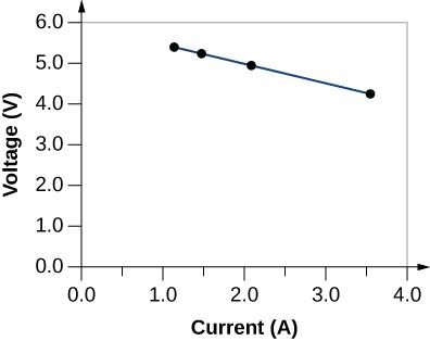
Measured terminal p.d. (V) is plotted against current (I) for a cell. The y-intercept gives E and the gradient equals –r, allowing e.m.f. and internal resistance to be determined experimentally. The graph includes a best-fit line with points labelled clearly; no extra concepts beyond the syllabus are shown. Source.
This linear relationship allows experimental determination of both the e.m.f. and internal resistance from simple voltage and current data, highlighting the significance of understanding terminal p.d. behaviour.
Energy Considerations
Energy Distribution Within the Source
The total electrical energy supplied by the source divides into:
Useful energy transferred to external components (corresponding to the terminal p.d.).
Wasted energy dissipated as heat inside the source (corresponding to lost volts).
Thus, the efficiency of a power source in delivering energy to an external circuit depends on the ratio of terminal p.d. to e.m.f.
EQUATION
—-----------------------------------------------------------------
Efficiency (η) = (V / E) × 100%
η = Percentage of total electrical energy delivered to the external circuit
—-----------------------------------------------------------------
A smaller internal resistance results in smaller lost volts and higher efficiency, which is particularly important in devices such as rechargeable batteries and power supplies.
Influence of Load Resistance
The relationship between internal resistance and external load resistance (R) determines how much of the source’s energy is usefully transferred:
When R >> r, most of the e.m.f. appears across the load; lost volts are small.
When R ≈ r, significant energy is wasted internally, and terminal p.d. falls noticeably.
When R << r, the majority of energy is dissipated inside the source, and terminal p.d. becomes very low.
This relationship also affects the current drawn and helps explain why batteries with high internal resistance cannot effectively power high-current devices.
Practical Implications and Measurement
Measuring Terminal Potential Difference
To measure terminal p.d. accurately:
Connect a voltmeter across the terminals of the source while it is supplying current.
Ensure the voltmeter has a high resistance to minimise current drawn, preventing further voltage drop.
By comparing open-circuit and closed-circuit readings, students can directly observe the concept of lost volts.
Effects of Age and Temperature
As a cell ages or discharges, internal resistance increases, leading to greater lost volts and reduced terminal p.d.
Higher temperature can temporarily reduce internal resistance, but prolonged heat can damage the cell and reduce lifespan.
These effects are vital for understanding practical battery performance in both laboratory experiments and real-world applications.
Summary of Key Relationships
Terminal p.d. (V) = e.m.f. (E) – lost volts (Ir)
Lost volts arise due to internal resistance (r) inside the source.
Increasing current increases lost volts and decreases terminal p.d.
The ratio of V/E represents the efficiency of energy transfer to the external circuit.
The interplay between terminal p.d., e.m.f., and lost volts underpins accurate circuit analysis and practical design in all real electrical systems.
Practice Questions
Question 1 (2 marks)
A student measures the open-circuit voltage of a cell as 1.50 V. When the cell is connected to a lamp, the current is 0.25 A and the terminal potential difference falls to 1.40 V.
(a) State what is meant by the terminal potential difference of a cell.
(b) Calculate the lost volts in the circuit.
Mark Scheme:
(a)
The potential difference across the terminals of a source when current flows (1)
It equals the energy transferred per unit charge to the external circuit (1)
(b)
Lost volts = e.m.f. – terminal p.d. = 1.50 – 1.40 = 0.10 V (1)
Question 2 (5 marks)
A battery of e.m.f. 12.0 V and internal resistance 1.5 Ω is connected to a variable resistor.
(a) Write an equation linking e.m.f. (E), current (I), load resistance (R) and internal resistance (r).
(b) Explain what is meant by the term lost volts.
(c) When the current in the circuit is 2.0 A, calculate:
(i) the terminal potential difference,
(ii) the power dissipated inside the battery.
(d) Describe how the terminal potential difference changes as current increases, and explain why.
Mark Scheme:
(a)
E = I(R + r) or E = V + Ir (1)
(b)
The voltage (potential difference) across the internal resistance of the source (1)
Represents energy per coulomb lost as heat within the source (1)
(c)(i)
V = E – Ir = 12.0 – (2.0 × 1.5) = 9.0 V (1)
(c)(ii)
Power dissipated inside battery = I²r = (2.0)² × 1.5 = 6.0 W (1)
(d)
As current increases, the voltage drop across the internal resistance (Ir) increases (1)
Therefore, terminal potential difference (V = E – Ir) decreases (1)
FAQ
Internal resistance arises mainly from the materials and chemical reactions inside the source.
The electrolyte and electrode materials impede charge movement, creating resistance.
As ions move through the electrolyte and electrons through connecting conductors, energy is dissipated as heat.
Ageing or chemical degradation increases internal resistance as reaction rates slow and material purity decreases.
Temperature also affects it — higher temperatures temporarily lower internal resistance by improving ion mobility.
As a battery discharges, chemical reactants are consumed, and the efficiency of the internal electrochemical reactions decreases.
This causes the internal resistance to rise.
More energy is lost as heat within the battery, so the voltage available to the external circuit (terminal p.d.) falls.
When the reactants are largely depleted, internal resistance becomes so high that the terminal p.d. drops sharply, signalling the battery is nearly exhausted.
To minimise internal resistance, designers can:
Use highly conductive materials for electrodes and connecting parts.
Select electrolytes with high ionic conductivity.
Increase the surface area of electrodes to reduce current density.
Keep the battery at an optimal temperature range to maintain ion mobility.
However, practical limits exist — safety, chemical stability, and cost restrict how much internal resistance can be reduced.
Measuring the open-circuit voltage gives the true e.m.f. of the cell, as no current flows and thus no lost volts occur.
This provides a baseline for comparison when current is later drawn from the cell.
By comparing open-circuit and loaded readings, one can determine:
The voltage drop caused by internal resistance.
The internal resistance value using the equation E – V = Ir.
This process ensures accurate analysis of the cell’s performance characteristics.
When cells are connected in series, both their e.m.f.s and internal resistances add up.
The total lost volts equal the sum of the voltage drops across each cell’s internal resistance.
The higher total internal resistance means a greater overall voltage drop when current flows.
As a result, while total e.m.f. increases, terminal p.d. may not rise proportionally if large current is drawn, especially in older or mismatched cells.
