
OCR Specification focus:
‘Use E = I(R + r) and E = V + Ir to model sources with internal resistance.’
Internal resistance determines how electrical energy within a power source is divided between useful output and wasted energy. Understanding its equations allows accurate prediction of circuit behaviour and performance.
The Concept of Internal Resistance
Every real electrical power source — such as a cell, battery, or power supply — possesses some internal resistance. This resistance causes part of the supplied electrical energy to be dissipated as heat within the source itself rather than being delivered to the external circuit.
Internal Resistance (r): The resistance inside a source of e.m.f. that opposes current flow and causes energy loss within the source itself.
When current flows, the internal resistance produces a voltage drop, meaning that the voltage available to the external circuit (the terminal potential difference) is less than the source’s full electromotive force (e.m.f.).
Electromotive Force (E): The total energy supplied per unit charge by a source when no current flows....
The internal resistance therefore represents the inefficiency inherent in all real sources. It becomes particularly significant in circuits drawing large currents, as the voltage lost within the source increases with current.
The Relationship Between e.m.f., Terminal Potential Difference, and Internal Resistance
When a current flows, part of the total energy supplied by the source is transferred to the internal resistor (r) and the rest is transferred to the external circuit load (R). The energy balance of this process is represented mathematically using two equivalent equations.
EQUATION
—-----------------------------------------------------------------
Equation for Internal Resistance: E = I(R + r)
E = electromotive force of the source (volts, V)
I = current flowing through the circuit (amperes, A)
R = external resistance of the circuit (ohms, Ω)
r = internal resistance of the source (ohms, Ω)
—-----------------------------------------------------------------
This equation shows that the e.m.f. equals the total potential difference across both the external load and the internal resistor. The product of current and resistance terms expresses the potential drops within and outside the source.
An alternative but equivalent way to represent this relationship focuses on measurable quantities — terminal potential difference (V) and current (I).
EQUATION
—-----------------------------------------------------------------
Alternative Equation for Internal Resistance: E = V + Ir
V = terminal potential difference (volts, V)
I = current through the circuit (amperes, A)
r = internal resistance of the source (ohms, Ω)
E = electromotive force of the source (volts, V)
—-----------------------------------------------------------------
Here, V represents the voltage available to the external circuit, while Ir represents the lost volts, the potential difference across the internal resistance. The sum of terminal potential difference and lost volts equals the total e.m.f. of the source.
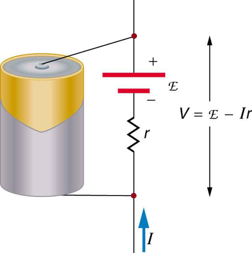
Schematic of a voltage source with internal resistance in series. The diagram labels the e.m.f. (E), the internal resistance (r), the current (I), and the terminal potential difference (V = E − Ir). This directly illustrates how ‘lost volts’ reduce the terminal p.d. when current flows. Source.
Between these two equations, students can model the behaviour of any practical electrical source under different load conditions.
Understanding Lost Volts
The lost volts represent energy that is not available to the external components of the circuit because it has been dissipated within the source. This concept explains why the terminal potential difference decreases as current increases.
Lost Volts: The potential difference across the internal resistance of a source, equal to Ir, representing the energy lost inside the source per coulomb of charge.
Because the lost volts increase proportionally with current, heavy loads drawing larger currents cause the terminal potential difference to drop noticeably, especially when the internal resistance is not negligible.
The equations allow prediction of this behaviour quantitatively, enabling analysis of how a real power source deviates from an ideal one.
Modelling Circuits with Internal Resistance
When modelling a power source with internal resistance, it is helpful to think of the internal resistance as a small resistor in series with an ideal voltage source of e.m.f. E. The combined circuit can then be treated using Kirchhoff’s laws or Ohm’s law, depending on the level of analysis required.
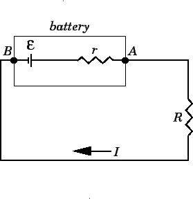
Circuit diagram of a battery with e.m.f. (E) and internal resistance (r) supplying a load (R). Because r is in series with R, the current is I = E/(R + r) and the terminal p.d. is V = E − Ir. This visual emphasises that internal resistance is part of the same current loop as the external resistor. Source.
The total resistance of the circuit equals the sum of the internal and external resistances, R_total = R + r.
The current in the circuit is determined by I = E / (R + r).
The terminal potential difference delivered to the external circuit is V = E − Ir.
The greater the ratio of external resistance to internal resistance, the smaller the proportion of energy wasted inside the source.
The power dissipated in each part of the circuit can be analysed as follows:
Power in external load: P_load = I²R
Power lost inside source: P_loss = I²r
These relationships allow evaluation of efficiency for a power supply, defined as the fraction of the total electrical power output that is delivered to the external circuit rather than lost internally.
Behaviour Under Different Load Conditions
The effect of internal resistance becomes more pronounced when the external resistance is low. Several key observations can be drawn from the equations:
When R >> r, almost all the e.m.f. appears across the external circuit; the source behaves almost ideally.
When R ≈ r, a significant fraction of energy is lost within the source, and the terminal potential difference is noticeably reduced.
When R = r, the circuit operates at maximum power output, as shown by the maximum power transfer theorem, though efficiency is only 50%.
When R < r, the source becomes inefficient and may overheat due to excessive internal energy dissipation.
Each case demonstrates how internal resistance limits performance and why understanding the relationship between E, V, I, R, and r is essential for accurate circuit design and analysis.
Practical Implications of the Internal Resistance Equations
Applying the equations E = I(R + r) and E = V + Ir enables prediction of how terminal voltage varies with load current — a relationship often displayed as a straight-line graph with gradient −r and intercept E. This graphical interpretation connects theoretical equations with experimental measurement, which is developed further in related subtopics.
Engineers and physicists use these equations to:
Design efficient power supplies and batteries.
Match internal resistance with load for maximum power or efficiency.
Evaluate the performance degradation of cells as internal resistance increases over time.
Interpret experimental data involving voltage, current, and power characteristics of electrical sources.
By mastering these equations, students gain the ability to model real electrical sources accurately, predict their limitations, and understand the crucial distinction between ideal and practical energy conversion in electrical systems.
Practice Questions
Question 1 (2 marks)
A cell has an electromotive force (e.m.f.) of 1.5 V and an internal resistance of 0.4 Ω. It is connected to a 2.6 Ω external resistor.
Calculate the terminal potential difference across the cell when current is flowing.
Mark Scheme:
Correct application of equation E = I(R + r) or rearranged form V = E − Ir (1 mark)
Correct substitution and final answer V = 1.5 − (I × 0.4), where I = 1.5 / 3.0 = 0.5 A, giving V = 1.3 V (1 mark)
Question 2 (5 marks)
A student investigates a power supply with internal resistance by measuring the terminal potential difference (V) for different currents (I) in a circuit.
(a) Explain how a straight-line graph can be used to determine both the e.m.f. and internal resistance of the power supply.
(b) Describe the expected shape of this graph and justify your reasoning using the equation E = V + Ir.
Mark Scheme:
States that plotting V (y-axis) against I (x-axis) gives a straight line (1 mark)
Identifies that the y-intercept = E, the electromotive force of the supply (1 mark)
Identifies that the gradient = −r, representing the negative internal resistance (1 mark)
Explains that as current increases, V decreases linearly due to increasing lost volts (Ir) (1 mark)
States that this relationship is derived from E = V + Ir, showing V = E − Ir, hence linear with negative slope (1 mark)
FAQ
As a cell ages or becomes discharged, its internal resistance usually increases. Chemical degradation, reduced electrolyte concentration, and build-up of by-products in the electrodes restrict the flow of charge carriers.
This rise in internal resistance causes a larger proportion of the e.m.f. to be lost as heat inside the cell, reducing terminal potential difference and efficiency under load. In rechargeable cells, the effect can be partly reversed through careful charging, but in non-rechargeable cells, it is irreversible.
Internal resistance is affected by the mobility of ions and the viscosity of the electrolyte.
At higher temperatures, ions move more freely, decreasing internal resistance and increasing terminal potential difference.
At lower temperatures, ion mobility decreases, resistance rises, and the cell delivers less power.
However, excessive heating can damage the cell or change chemical reactions, permanently increasing internal resistance.
For a.c. sources such as signal generators or transformers, internal resistance is often referred to as output impedance. This may include both resistive and reactive (inductive or capacitive) components.
The total impedance affects how much of the generated voltage appears across the external circuit. Matching the source’s output impedance to the load ensures maximum power transfer, following the same principle as in d.c. circuits with internal resistance.
Engineers use several techniques to minimise internal resistance and energy loss:
Employ low-resistivity materials such as copper and silver for internal conductors.
Optimise electrode surface area to enhance ion exchange.
Use electrolytes with high ionic conductivity.
Arrange multiple cells in parallel to share current and reduce effective internal resistance.
Reducing internal resistance improves energy efficiency, terminal voltage stability, and battery lifespan.
This equation expresses the conservation of electrical energy within a source. The total energy supplied per unit charge by the e.m.f. (E) divides into two parts:
V, the useful energy per coulomb delivered to the external circuit.
Ir, the energy per coulomb lost inside the source as heat due to internal resistance.
Thus, it accounts for all energy transformations within the source, confirming that no energy is unaccounted for, only redistributed between internal and external components.
