
OCR Specification focus:
‘For two resistors: V_out = (R₂/(R₁+R₂)) V_in and V₂/V₁ = R₂/R₁.’
Potential dividers are essential for understanding how voltage is distributed in electrical circuits. They enable control of output voltage and are fundamental to sensing and measurement systems.
The Concept of a Potential Divider
A potential divider is an arrangement of resistors connected in series across a voltage supply. It allows part of the supply voltage to be taken from the junction between the resistors to provide a reduced output voltage.
The fundamental idea is that the total voltage supplied is shared among the resistors in proportion to their resistances. The larger the resistance, the greater the share of the total potential difference it receives.
Potential Divider: A circuit that uses two or more resistors in series to divide an input voltage into smaller output voltages.
Potential dividers are frequently used to produce a variable output voltage, supply reference voltages, or sense environmental changes when used with sensors such as thermistors or LDRs.
Voltage Distribution in Series Circuits
When resistors are connected in series, the same current (I) flows through each component. The potential difference (V) across each resistor depends on its resistance value. According to Ohm’s law, V=IRV = IRV=IR, so a resistor with higher resistance has a higher potential difference across it for the same current.
The total voltage across the resistors equals the sum of the individual voltages, ensuring energy conservation in accordance with Kirchhoff’s second law. This law states that the total electromotive force (emf) in a closed loop equals the sum of the potential drops around that loop.
To analyse a two-resistor divider, consider resistors R1R_1R1 and R2R_2R2 connected in series across an input voltage VinV_{in}Vin. The output voltage VoutV_{out}Vout is taken across R2R_2R2.
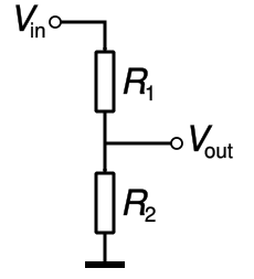
Schematic of a two-resistor potential divider with R₁ and R₂ in series across V_in, taking V_out across R₂. The image illustrates that the output depends on the resistance ratio, not absolute values. Labels are clear and kept to the essentials for equation use. Source.
EQUATION
—-----------------------------------------------------------------
Potential Divider Equation (V_out) = (R₂ / (R₁ + R₂)) × V_in
V_out = Voltage across resistor R₂ (volts, V)
R₁ = Resistance of first resistor (ohms, Ω)
R₂ = Resistance of second resistor (ohms, Ω)
V_in = Input voltage across both resistors (volts, V)
—-----------------------------------------------------------------
This relationship shows that V_out depends on the ratio of the resistances rather than their absolute values. Changing the ratio alters the output voltage.
Deriving the Potential Divider Equation
From Ohm’s law, the current through the series circuit is the same for both resistors:
EQUATION
—-----------------------------------------------------------------
Current (I) = V_in / (R₁ + R₂)
I = Current through the circuit (amperes, A)
V_in = Input voltage (volts, V)
R₁, R₂ = Series resistances (ohms, Ω)
—-----------------------------------------------------------------
The potential difference across R2R_2R2 is then Vout=IR2V_{out} = IR_2Vout=IR2. Substituting for III gives:
Vout=Vin×(R2/(R1+R2))V_{out} = V_{in} × (R₂ / (R₁ + R₂))Vout=Vin×(R2/(R1+R2)).
This formula forms the basis for analysing voltage ratios in divider circuits.
Understanding Voltage Ratios
The voltage ratio between two resistors in a potential divider is proportional to their resistance ratio. This can be expressed as:
EQUATION
—-----------------------------------------------------------------
Voltage Ratio (V₂/V₁) = R₂ / R₁
V₂ = Voltage across R₂ (volts, V)
V₁ = Voltage across R₁ (volts, V)
R₁, R₂ = Series resistances (ohms, Ω)
—-----------------------------------------------------------------
This means doubling R2R₂R2 while keeping R1R₁R1 constant will double V2V₂V2 relative to V1V₁V1. This proportionality is what makes potential dividers useful for setting controlled voltage levels in circuits.
Behaviour of the Potential Divider
When the resistors are fixed, the divider produces a constant output voltage determined by the resistance ratio. However, replacing one resistor with a variable resistor such as a potentiometer, LDR, or thermistor allows the output voltage to change with position, light intensity, or temperature.
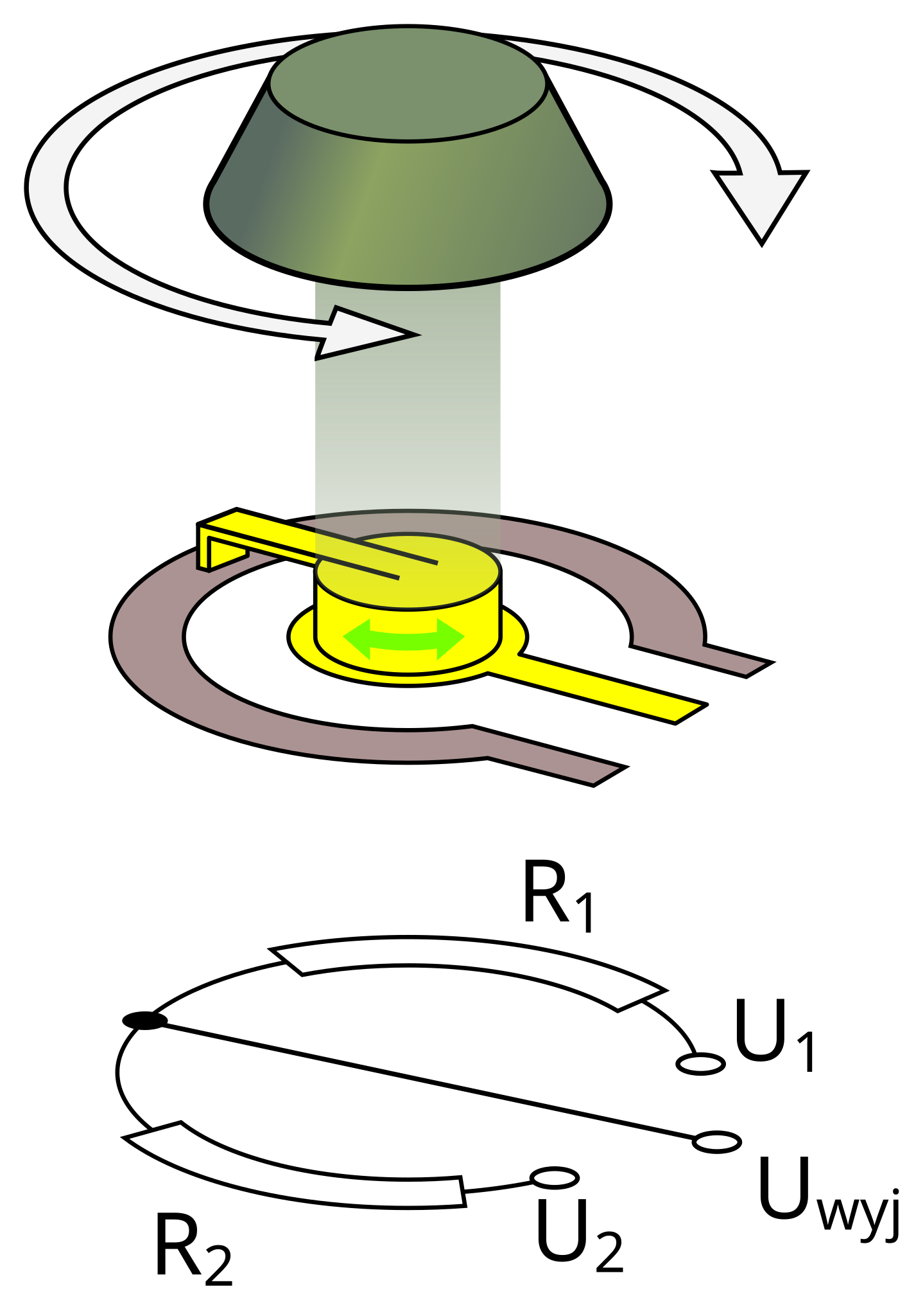
Diagram of a potentiometer acting as a variable potential divider, with a wiper tapping a fraction of the total resistance to set V_out. The labels make clear how adjusting the wiper changes the resistance ratio. This illustration includes physical/rotational details beyond the syllabus equation, but these aid interpretation of the same divider relationship. Source.
Key Characteristics
Voltage is shared between resistors in direct proportion to their resistance.
Current remains constant through all series components.
Output voltage is adjustable by varying one resistance or altering the ratio.
Energy is conserved — the sum of voltage drops equals the supply voltage.
Divider circuits do not amplify power; they redistribute it according to resistance.
Designing Potential Divider Circuits
To design a potential divider for a specific output voltage:
Select the input voltage (the supply voltage).
Choose a desired output voltage.
Rearrange the divider equation to determine the necessary resistor ratio.
Select standard resistor values that closely achieve this ratio.
Ensure current is limited to prevent excessive power dissipation.
Because the output depends only on resistance ratios, using high-value resistors minimises current draw and energy loss, improving efficiency.
When the potential divider is connected to a load, the circuit’s behaviour changes. The load introduces an additional resistance in parallel with the output resistor, reducing the effective resistance and altering VoutV_{out}Vout. This is known as the loading effect and must be considered in circuit design.
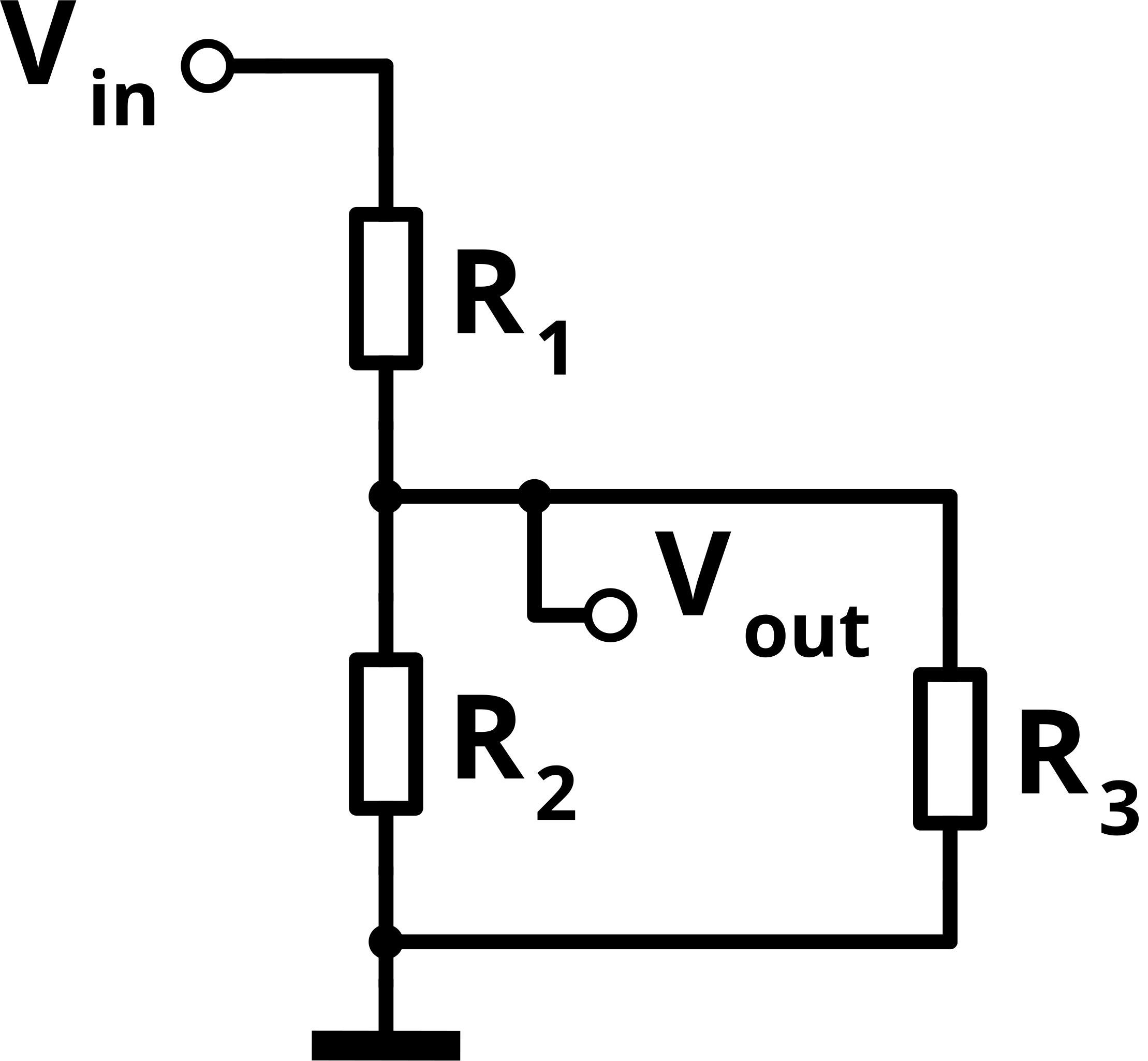
A potential divider with a load resistor connected in parallel with R₂, illustrating how the effective resistance decreases and V_out drops. This visual supports discussion of loading effects and why divider calculations must consider attached circuitry. The image includes only the elements necessary for analysis; no unrelated components are shown. Source.
Application in Measurement and Control
Potential dividers are widely used in:
Sensor circuits, where the resistance of an LDR or thermistor varies with environmental conditions.
Audio controls, where potentiometers adjust signal amplitude.
Microcontroller interfaces, providing reference voltages or scaling down voltages for safe input.
Battery monitoring, where dividers allow small fractions of high voltages to be measured safely.
The design must ensure that the output impedance of the divider is low enough not to distort readings, especially when feeding high-impedance measuring devices or analogue-to-digital converters.
Practical Considerations
When constructing potential dividers:
Use precise, low-tolerance resistors for accurate voltage division.
Check power ratings; resistors must handle the power dissipated as heat.
Minimise unwanted current loss by selecting high resistance values when feasible.
Avoid very small resistances, as they may cause excessive current and heating.
Consider temperature coefficients — resistance may change slightly with temperature.
Potential dividers form the foundation of analogue signal processing in physics and electronics, making understanding their equations and practical use essential for accurate circuit analysis and design.
Practice Questions
Question 1 (2 marks)
A potential divider consists of two fixed resistors, R1 = 4.0 kΩ and R2 = 6.0 kΩ, connected in series across a 12.0 V supply.
Calculate the output voltage across R2.
Mark Scheme:
Correct use of the potential divider equation: Vout = (R2 / (R1 + R2)) × Vin (1 mark)
Substitution and correct calculation: (6.0 / (4.0 + 6.0)) × 12.0 = 7.2 V (1 mark)
Question 2 (5 marks)
A student designs a potential divider to provide a variable output voltage for a temperature-sensing circuit. The circuit uses a fixed resistor of 2.0 kΩ and a thermistor whose resistance decreases with temperature. The circuit is powered by a 9.0 V supply.
(a) Explain qualitatively how the output voltage across the thermistor changes as the temperature increases. (2 marks)
(b) State and explain one factor the student should consider when choosing resistor values to ensure the circuit operates effectively as a sensor system. (3 marks)
Mark Scheme:
(a)
States that as temperature increases, thermistor resistance decreases (1 mark)
Explains that since Rthermistor decreases, the voltage across it (Vout) also decreases because it receives a smaller share of the supply voltage (1 mark)
(b)
Any one valid factor with reasoning:
Resistor ratio consideration: Choose Rfixed and Rthermistor values so the output voltage changes significantly over the operating temperature range (1 mark).
Minimising current/power loss: Use sufficiently large resistor values to avoid excessive current and heating (1 mark).
Avoiding loading effects: Ensure the sensor’s output is not significantly affected by the input impedance of any measuring device (1 mark).
Clear reasoning linked to the chosen factor (up to 2 marks total for detailed explanation).
FAQ
Doubling both resistors does not change the output voltage. The ratio R2 / (R1 + R2) remains the same, so Vout is unaffected.
However, the current in the circuit decreases because total resistance has increased, which means less power is dissipated.
This principle allows designers to use larger resistor values to minimise energy losses without changing voltage ratios.
Taking the output across the lower resistor (R2) allows Vout to be smaller than the supply voltage, which is often the desired control voltage for sensors or input devices.
If taken across the upper resistor (R1), the output would represent the complementary voltage (Vin − Vout), which is less convenient for most applications.
Choosing where to take the output depends on whether the required signal should increase or decrease with changes in the variable resistor.
A voltmeter has very high but finite resistance. When connected across the output resistor, it forms a parallel branch.
This slightly reduces the effective resistance across R2, which in turn reduces the output voltage.
High-impedance voltmeters are used to minimise this loading effect, ensuring accurate voltage readings in experimental and sensor circuits.
A stable reference voltage is produced by using two fixed resistors with precise, low-tolerance values.
The resistors are chosen so the output voltage equals the desired reference level.
A stable supply voltage and low temperature coefficients prevent drift in resistance values.
Such dividers are common in analogue circuits and calibration systems where a constant reference voltage is needed.
Potential dividers are not suitable for supplying significant power because the resistors themselves dissipate energy.
When connected to a low-resistance load, the effective resistance changes, altering Vout and reducing efficiency.
Most of the supply power is converted into heat in the resistors rather than being transferred to the load.
Therefore, potential dividers are used mainly for voltage control and signal conditioning, not for power delivery.
