
OCR Specification focus:
‘Investigate refraction and total internal reflection with ray boxes and transparent blocks.’
Investigating Refraction and Total Internal Reflection
Light changes direction when it passes between materials with different optical densities, such as air and glass. Understanding and investigating refraction and total internal reflection (TIR) provides essential insight into how light behaves at boundaries — a core concept for optical technologies like fibre optics, prisms, and lenses.
Refraction of Light
Refraction occurs when a wave crosses the boundary between two media, causing a change in its speed and direction. The bending of light depends on how much slower or faster it travels in the new medium.
Refraction: The change in direction of a wave as it passes from one medium to another due to a change in wave speed.
When light travels from air (a less dense medium) into glass (a more optically dense medium), it slows down and bends towards the normal. When it passes from glass to air, it speeds up and bends away from the normal.
This behaviour can be studied using ray boxes and transparent blocks such as rectangular glass or perspex prisms.
Experimental Investigation of Refraction
A typical refraction experiment helps verify the relationship between the angle of incidence and refraction. The following steps outline a standard method used in the OCR Physics course:
Using a Ray Box and Transparent Block
Setup:
Place a rectangular glass block on a sheet of paper.
Trace its outline.
Use a ray box to project a narrow ray of light at an angle onto one face of the block.
Measuring Angles:
Mark the incident ray, refracted ray, and emergent ray.
Remove the block and draw the normal line at the point where the incident ray meets the block.
Measure the angle of incidence (i) and angle of refraction (r) using a protractor.
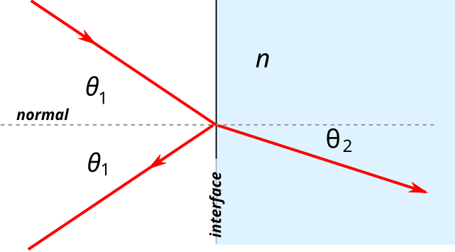
Diagram of reflection and refraction at a plane boundary, with angles measured to the normal. This visual reinforces how i and r are defined experimentally for OCR tasks. Extra detail is minimal and fully aligned with the syllabus focus. Source.
Observations:
The ray bends towards the normal as it enters the block.
Inside the block, the light travels in a straight line.
On exiting, it bends away from the normal.
Analysis:
Plot a graph of sin i against sin r.
The gradient gives the refractive index of the material.
Refractive Index
The refractive index quantifies how much light slows down in a medium compared to in a vacuum.
EQUATION
—-----------------------------------------------------------------
Refractive Index (n) = c / v
c = Speed of light in a vacuum (3.00 × 10⁸ m s⁻¹)
v = Speed of light in the medium (m s⁻¹)
—-----------------------------------------------------------------
A higher refractive index indicates greater optical density. For example, glass (n ≈ 1.5) slows light more than air (n ≈ 1.0).
At a boundary between two media, n sin i = constant, which is derived from Snell’s law. This law allows us to calculate unknown angles of refraction when light passes between materials.
Relationship Between Speed, Angle, and Direction
When a wave passes into a medium with a higher refractive index:
The wavefronts shorten.
The frequency remains constant.
The speed and wavelength decrease.
The ray bends towards the normal.
Conversely, moving into a less dense medium causes the ray to bend away from the normal, with increased wave speed and wavelength.
This relationship explains why a straw appears bent when partially submerged in water — a classic example of refraction.
Total Internal Reflection (TIR)
When light attempts to move from a denser to a less dense medium, such as glass to air, it can be reflected entirely back into the original medium under certain conditions. This is total internal reflection.
Total Internal Reflection: The phenomenon where light is completely reflected inside a denser medium when the angle of incidence exceeds the critical angle.
Two conditions must be satisfied:
The light must travel from a higher to a lower refractive index (e.g. glass to air).
The angle of incidence must be greater than the critical angle (C).
Below the critical angle, refraction and partial reflection occur simultaneously. At exactly the critical angle, the refracted ray travels along the boundary. Beyond this angle, no refraction occurs — all light is reflected internally.
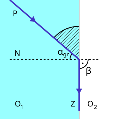
Schematic of total internal reflection at the critical angle, with the boundary-parallel transmitted ray and internal reflection shown. This diagram supports the sin C = 1/n relationship used to determine refractive index. No extraneous detail beyond the OCR scope is included. Source.
Investigating TIR Experimentally
Using a Semicircular Glass Block
Setup:
Place a semicircular glass block on paper with its flat side facing the incoming ray.
Shine a narrow beam from a ray box through the curved surface towards the centre, ensuring it strikes the flat face.
Procedure:
Gradually increase the angle of incidence at the flat face.
Observe how the refracted ray bends further away from the normal.
Identify the critical angle when the refracted ray travels along the surface.
Beyond this, observe total internal reflection.
Analysis:
Measure the critical angle (C) using a protractor.
Use the following equation to calculate the refractive index of the block.
EQUATION
—-----------------------------------------------------------------
Critical Angle Relationship: sin C = 1 / n
C = Critical angle (°)
n = Refractive index of the material (no unit)
—-----------------------------------------------------------------
This simple yet precise experiment visually demonstrates the transition from refraction to total internal reflection.
Applications of Total Internal Reflection
The phenomenon of TIR has several significant practical uses, based on its ability to efficiently reflect light without energy loss:
Optical fibres: Used for data transmission in telecommunications and medicine; light signals reflect repeatedly within the fibre core, maintaining intensity over long distances.
Prisms in binoculars and cameras: Redirect light paths without absorption losses.
Periscopes and endoscopes: Utilise TIR to transmit clear images through complex pathways.
By experimenting with ray boxes and transparent materials, students directly observe the underlying laws of refraction and TIR, connecting theory with tangible visual evidence — a vital component of mastering wave behaviour in optics.
Practice Questions
Question 1 (2 marks)
A ray of light passes from air into glass at an angle of incidence of 35°. The angle of refraction is 22°.
(a) Explain why the light ray bends towards the normal as it enters the glass.
Mark scheme:
(1 mark) States that light travels more slowly in glass than in air.
(1 mark) States that the decrease in speed causes the ray to bend towards the normal.
Question 2 (5 marks)
A student investigates total internal reflection using a semicircular glass block. The refractive index of the glass is 1.52.
(a) Calculate the critical angle for light travelling from the glass into air.
(b) Describe how the student could use a ray box and protractor to observe total internal reflection experimentally, and explain what would be seen as the angle of incidence increases.
Mark scheme:
(a) Calculation (2 marks):
(1 mark) States or uses correct equation: sin C = 1 / n.
(1 mark) Substitutes and calculates: C = sin⁻¹(1 / 1.52) = 41.1° (accept 41° to 42°).
(b) Description and explanation (3 marks):
(1 mark) Describes shining a ray from the curved surface of a semicircular glass block towards the centre of the flat face to avoid refraction on entry.
(1 mark) States that as the angle of incidence increases, the refracted ray moves closer to the surface until it travels along the boundary at the critical angle.
(1 mark) States that beyond the critical angle, no refraction occurs and all the light is reflected internally (total internal reflection).
FAQ
Partial reflection happens because not all the light’s energy is transmitted into the second medium. Some of it is reflected due to the difference in refractive indices.
At the boundary, the electric field components of the wave interact differently depending on the material’s optical density. This mismatch in impedance leads to both reflection and refraction occurring simultaneously — except at the critical angle, where the refracted ray runs along the boundary.
A semicircular block ensures the light ray always strikes the flat surface at normal incidence to the curved face, preventing unwanted refraction on entry.
This means that any refraction or reflection observed at the flat surface is due solely to the boundary between the glass and air. The geometry guarantees accuracy when measuring the critical angle, as the incident angle at the flat face equals the angle inside the glass.
Different wavelengths of light refract by different amounts because the refractive index of a material depends on wavelength — a phenomenon known as dispersion.
Shorter wavelengths (blue/violet light) slow down more and bend closer to the normal.
Longer wavelengths (red light) bend less.
This explains why white light separates into a spectrum when passing through a prism, though such dispersion effects are typically beyond what’s observed in basic OCR refraction experiments.
Common sources of error include:
Parallax error when aligning the protractor or marking rays.
Ray thickness, which can make angle measurement uncertain.
Misplacement of the normal line, slightly shifting the measured incidence or refraction angles.
Surface imperfections on the block causing scattering or irregular refraction.
To minimise these errors, students should use a narrow ray, sharp pencil lines, and view from directly above when marking and measuring.
As the angle of incidence inside the denser medium increases, the refracted ray at the boundary moves closer to the surface.
At the critical angle, the refracted ray travels exactly along the boundary. Increasing the angle further makes this refracted ray disappear, leaving only a bright internally reflected beam.
This sudden disappearance of the external beam is a clear, observable indicator that total internal reflection has just begun.
