
OCR Specification focus:
‘Perform two-source interference experiments using sound and microwaves; explain fringe patterns.’
Two-source interference is a fundamental demonstration of wave behaviour, showing how identical waves from separate sources combine to produce regions of reinforcement and cancellation. This reveals the underlying principles of superposition and coherence in a clear, measurable way.
Understanding Two-Source Interference
Two-source interference occurs when two coherent waves overlap, leading to alternating regions of constructive and destructive interference. This can be observed for many types of waves, including sound and microwaves, both of which provide accessible experimental examples for investigating interference patterns.
Coherence and Phase Relationship
For observable interference patterns, the two sources must be coherent.
Coherence: When two waves have a constant phase difference and the same frequency.
Coherent sources maintain a fixed relationship between their phases, ensuring that the interference pattern remains stable over time. If the sources are not coherent, the phase relationship varies randomly, causing the pattern to fluctuate or disappear.
In two-source experiments, coherence is usually achieved by splitting a single wave source into two, rather than using two independent generators.
The Principle of Superposition
The principle of superposition states that when two or more waves overlap, the resultant displacement at any point is the vector sum of the individual displacements.
Constructive interference occurs when waves are in phase—their peaks and troughs coincide—producing a resultant wave of greater amplitude. Destructive interference occurs when waves are out of phase by half a wavelength (180°), leading to partial or complete cancellation.
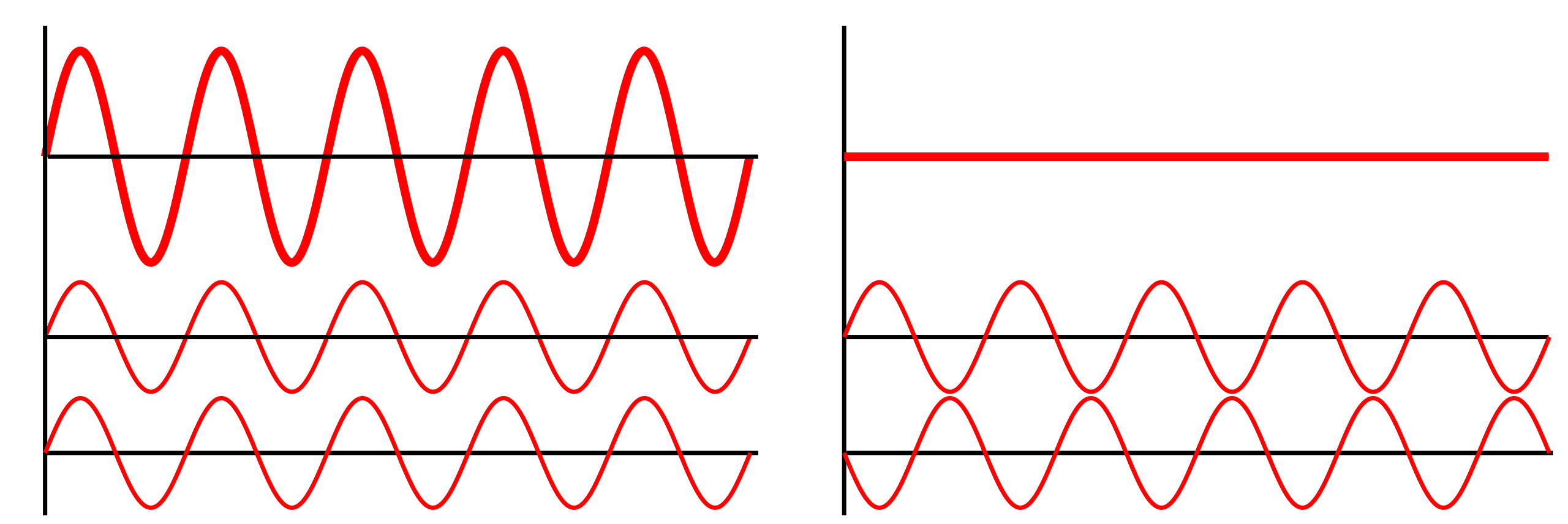
Superposition of two coherent waves: left shows in-phase addition yielding a larger resultant amplitude; right shows 180° out-of-phase addition producing cancellation. This illustrates the phase conditions used to predict loud (maxima) and quiet (minima) regions in two-source sound or microwave fields. The diagram is deliberately minimal and does not add syllabus-external content. Source.
EQUATION
—-----------------------------------------------------------------
Condition for Constructive Interference: Path difference = nλ
n = integer (0, 1, 2, …)
λ = wavelength of the waves (metres, m)
Condition for Destructive Interference: Path difference = (n + ½)λ
n = integer (0, 1, 2, …)
λ = wavelength of the waves (metres, m)
—-----------------------------------------------------------------
These path difference conditions determine where maxima (bright or loud regions) and minima (dark or quiet regions) occur in the interference pattern.
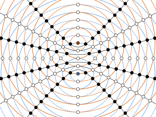
Interference from two coherent sources forms alternating maxima and minima where the path difference equals integer or half-integer multiples of the wavelength. The white points mark constructive interference and the black points destructive interference; the black curves are hyperbolae of constant path difference. This geometry applies to sound and microwaves when the sources are coherent. Source.
Two-Source Interference Using Sound
Equipment and Setup
Two-source interference with sound can be demonstrated using:
Two loudspeakers connected to the same signal generator.
A microphone or human ear to detect sound intensity changes.
A signal generator producing a single frequency, ensuring coherence.
The loudspeakers act as coherent sources emitting sound waves of identical frequency and amplitude. The interference pattern forms in the air between them.
Observations and Pattern Formation
As a listener or microphone moves perpendicular to the line joining the two speakers, alternating regions of loud and quiet sound are detected.
Loud regions correspond to constructive interference.
Quiet regions correspond to destructive interference.
The separation between adjacent loud (or quiet) points corresponds to one-half of a wavelength of the emitted sound.
The distance between speakers, the wavelength, and the observation position determine the pattern spacing. Shorter wavelengths (higher frequencies) lead to smaller spacing between maxima and minima.
Two-Source Interference Using Microwaves
Equipment and Setup
Two-source microwave interference experiments typically use:
A microwave transmitter (emitter).
A microwave receiver (detector).
A microwave splitter or reflective system to create two coherent sources.
Microwave absorbers to reduce unwanted reflections.
Microwaves have much shorter wavelengths than sound, allowing for interference patterns to be mapped precisely using detectors.
Measuring and Mapping the Interference Pattern
The detector measures signal strength as it moves across the interference field. Points of maximum intensity correspond to constructive interference, while minima correspond to destructive interference.
These patterns appear as fringes or bands of alternating signal strength.
The pattern spacing depends on the wavelength and distance between sources.
By measuring the positions of maxima and knowing the geometry of the setup, the wavelength of the microwaves can be calculated, confirming the wave nature of electromagnetic radiation.
EQUATION
—-----------------------------------------------------------------
Wave Speed (v) = Frequency (f) × Wavelength (λ)
v = wave speed (metres per second, m s⁻¹)
f = frequency (hertz, Hz)
λ = wavelength (metres, m)
—-----------------------------------------------------------------
This equation allows determination of unknown quantities such as wavelength when the speed and frequency are known, reinforcing the link between measurable interference patterns and wave properties.
Comparing Sound and Microwave Interference
Both sound and microwaves display identical interference principles because the underlying mechanism—superposition of coherent waves—is universal. However, differences arise due to their physical nature:
Sound waves are longitudinal, requiring a medium.
Microwaves are transverse electromagnetic waves that can propagate through a vacuum.
Despite these differences, both demonstrate:
Fringe or nodal patterns indicating alternating constructive and destructive interference.
Dependence of pattern spacing on wavelength and source separation.
The necessity for coherence for stable interference fringes.
In both cases, the visibility or detectability of the pattern relies on precision alignment and the use of identical frequency sources.
Explanation of Fringe Patterns
Fringes represent alternating regions of maximum and minimum wave intensity caused by the consistent path difference between the two sources.
Fringe Pattern: The spatial variation of intensity resulting from interference between coherent waves, producing alternating maxima and minima.
The position of each fringe can be described geometrically in terms of wavelength and the distance between sources. For small angles, the spacing between fringes (Δx) increases with longer wavelengths and decreases with greater source separation.
The symmetry and regularity of these patterns provide strong evidence for the wave nature of sound and electromagnetic radiation. When measured accurately, they allow direct determination of wavelengths, confirming fundamental properties predicted by wave theory.
Through the analysis of two-source interference in sound and microwaves, students gain an essential understanding of how superposition, coherence, and path difference combine to produce measurable and predictable physical phenomena that exemplify wave behaviour in diverse contexts.
Practice Questions
Question 1 (2 marks)
State the conditions required to observe a stable interference pattern in a two-source sound or microwave experiment.
Mark Scheme:
(1 mark) Both sources must emit waves of the same frequency and wavelength.
(1 mark) The two sources must be coherent, meaning they have a constant phase difference.
Question 2 (5 marks)
In a two-source microwave interference experiment, a detector is moved across the interference field and records alternating maxima and minima of signal strength.
(a) Explain how these maxima and minima arise.
(b) Describe how the experiment can be used to determine the wavelength of the microwaves.
Mark Scheme:
(a) Explanation of maxima and minima (3 marks total)
(1 mark) Constructive interference occurs where waves from the two sources arrive in phase (path difference = nλ).
(1 mark) Destructive interference occurs where waves arrive out of phase by 180° (path difference = (n + ½)λ).
(1 mark) The pattern of alternating maxima and minima is produced by the superposition of the two coherent waves.
(b) Determining wavelength (2 marks total)
(1 mark) Measure the distance between adjacent maxima (or minima) across the field; this distance corresponds to half the wavelength.
(1 mark) Calculate the wavelength using λ = 2 × (distance between successive maxima or minima).
FAQ
Using a single signal generator ensures both sources emit waves of the same frequency and phase relationship, producing coherent waves. Independent sources would drift in frequency and phase, destroying the fixed interference pattern.
In practice, the generator’s output is split equally to each source, ensuring identical wave characteristics and stable interference fringes. This method is essential for both sound and microwave interference demonstrations.
Moving one source changes the path difference between waves reaching any point in the observation field.
Fringes shift position, since constructive and destructive regions realign.
The spacing between fringes usually remains the same (as it depends on wavelength and separation).
Large shifts can cause loss of overlap or coherence, reducing fringe visibility.
This demonstrates the sensitivity of interference to geometry and alignment.
Microwaves and sound waves have longer wavelengths (millimetres to metres) than visible light (hundreds of nanometres).
Longer wavelengths make path differences measurable with ordinary equipment.
Detectors and microphones easily record intensity changes.
The apparatus allows direct observation of maxima and minima, unlike light fringes that require precision optics and narrow slits.
This makes sound and microwaves ideal for teaching the underlying interference principles.
To enhance fringe clarity:
Use a pure tone (single frequency) to ensure good coherence.
Minimise background noise and reflections from walls or surfaces.
Match the amplitudes of both loudspeakers to ensure symmetrical interference.
Maintain a fixed distance between sources to prevent phase drift.
These factors increase the contrast between loud and quiet regions, making interference effects easier to detect.
Yes, interference still occurs, but the pattern becomes uneven.
Where amplitudes differ, complete cancellation at destructive points is no longer possible.
The maxima remain but are reduced in contrast, and minima may not reach zero intensity.
The overall visibility (fringe contrast) depends on how similar the amplitudes are — perfect interference requires waves of equal amplitude and coherence.
