
OCR Specification focus:
‘Young’s double-slit gives classical evidence of light’s wave nature; use y = Dλ/a and gratings.’
The Young double-slit experiment provides powerful evidence for the wave nature of light, allowing accurate wavelength determination through the analysis of interference fringes produced when coherent light passes through two narrow slits.
The Principle of the Young Double-Slit Experiment
The Young double-slit experiment, first performed by Thomas Young in 1801, demonstrates how light behaves as a wave rather than a stream of particles. When coherent light — light with a constant phase difference and the same frequency — passes through two narrow, closely spaced slits, it diffracts and the emerging waves overlap.
Where these diffracted waves meet, they interfere, producing a pattern of bright and dark fringes on a distant screen. This interference pattern arises because of variations in path difference between waves from the two slits.
Conditions for Interference
For a stable and observable interference pattern:
The two slits must be narrow and close together (typically separated by a distance less than a millimetre).
The light source must be monochromatic (single wavelength) and coherent.
The screen must be placed sufficiently far away so that overlapping waves form clearly defined fringes.
These conditions ensure that each point on the screen receives light from both slits with a measurable path difference.
Constructive and Destructive Interference
Constructive interference occurs when waves arrive in phase, reinforcing each other to produce bright fringes.
Destructive interference happens when waves arrive out of phase by half a wavelength, cancelling each other to form dark fringes.
This regular alternation of bright and dark regions forms the interference pattern central to Young’s experiment.
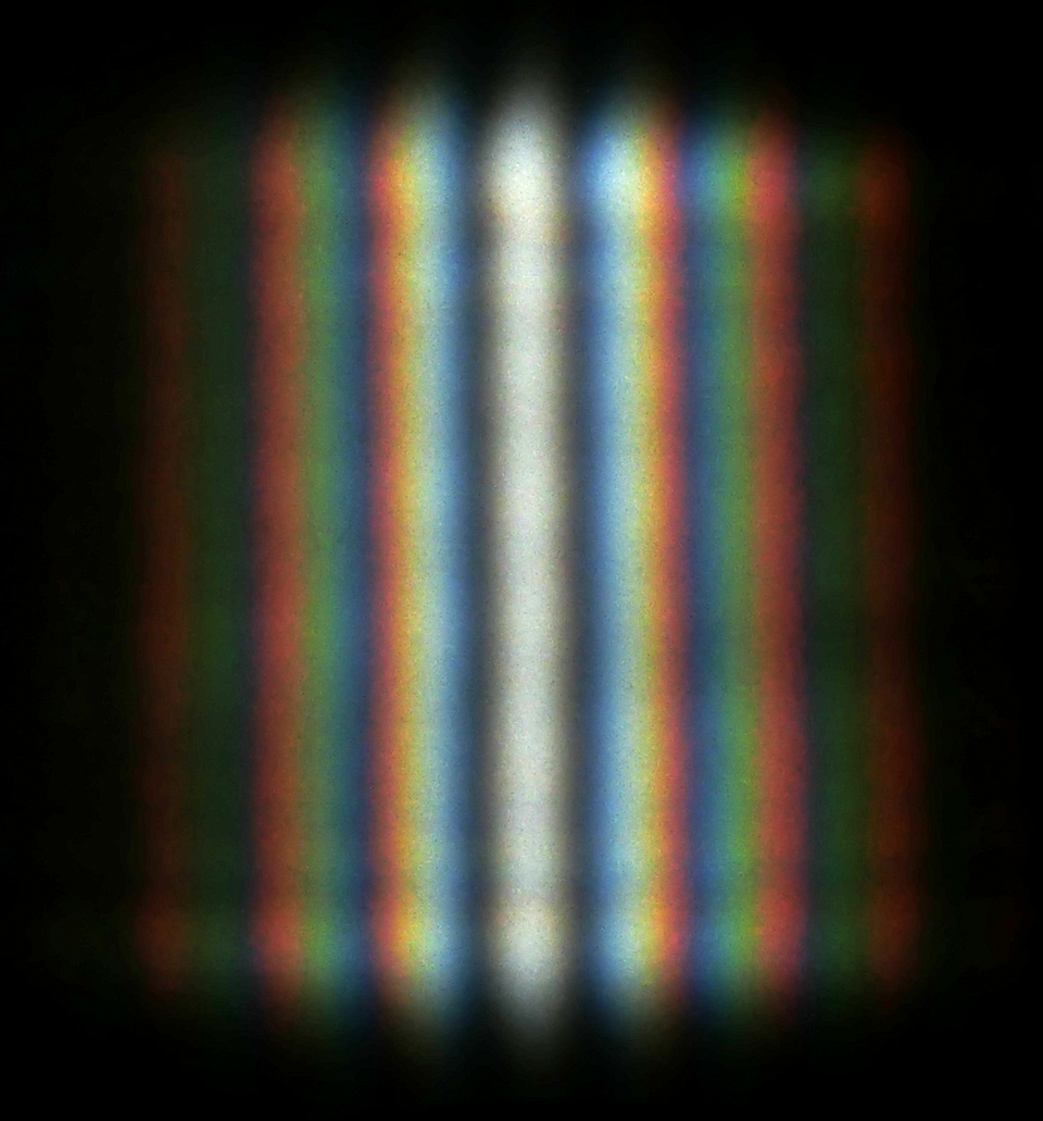
Double-slit interference pattern recorded with narrow, closely spaced slits. Bright maxima arise where waves arrive in phase; dark minima occur where they arrive out of phase by half a wavelength. Minor edge effects at the slit boundaries are visible but do not alter the core pattern relevant to A-Level treatment. Source.
Path Difference and Fringe Formation
At the screen, each bright or dark fringe corresponds to a specific path difference (Δx) between the two slits’ light rays.
Constructive interference: Path difference = nλ
Destructive interference: Path difference = (n + ½)λ
where n is an integer (0, 1, 2, 3, …).
The centre of the pattern, called the central maximum, occurs where the path difference is zero.
Measuring the Wavelength of Light
The position of the fringes can be related to the wavelength (λ) of the light through geometric reasoning. When the distance between the slits is small compared with the distance to the screen, the angles involved are small, and tan θ ≈ sin θ ≈ θ (in radians). This leads to the essential equation for the Young double-slit experiment.
EQUATION
—-----------------------------------------------------------------
Young’s Double-Slit Equation (λ) = (a × y) / D
λ = Wavelength of the light (m)
a = Slit separation (m)
y = Fringe spacing between adjacent bright (or dark) fringes (m)
D = Distance from slits to the screen (m)
—-----------------------------------------------------------------
The relationship shows that wavelength is directly proportional to fringe spacing, allowing λ to be determined experimentally by measuring y, D, and a.
Experimental Setup
To perform the Young double-slit experiment:
Use a coherent light source, such as a laser, to illuminate a pair of narrow, parallel slits.
The light diffracts at each slit and overlaps, producing interference fringes on a distant screen.
Measure fringe spacing (y) with a ruler or travelling microscope.
Record D, the distance between the slits and the screen, and a, the slit separation, often determined with a micrometer or diffraction grating.
These measurements allow precise calculation of the wavelength.
Understanding Diffraction Gratings
A diffraction grating is an optical component with a very large number of evenly spaced slits, typically hundreds per millimetre. When monochromatic light passes through such a grating, the diffracted beams interfere to produce sharp, bright maxima at specific angles.
EQUATION
—-----------------------------------------------------------------
Diffraction Grating Equation (nλ) = d × sin θ
n = Order of the maximum (integer)
λ = Wavelength (m)
d = Grating spacing (m) = 1 / (number of lines per metre)
θ = Diffraction angle for the nth order (radians or degrees)
—-----------------------------------------------------------------
Each order maximum corresponds to an integer value of n where waves from adjacent slits interfere constructively. This equation provides another means to determine λ, with high accuracy due to the sharpness of diffraction maxima.
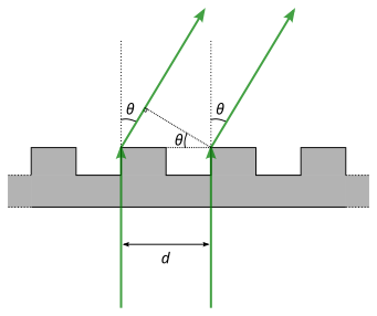
Transmission diffraction grating diagram indicating constructive interference when path differences equal integer multiples of λ. It visualises the grating equation nλ = d sin θ, consistent with the text’s discussion. The figure includes brief ray-phase annotation not required by OCR but helpful for interpreting order maxima. Source.
The Wave Nature of Light
The success of Young’s experiment in producing a stable interference pattern demonstrated that light behaves as a wave, because interference requires the superposition of oscillating disturbances.
Before Young’s demonstration, light was widely believed to consist of particles (the Newtonian corpuscular theory). The observed interference fringes could not be explained by a particle model, as particles do not cancel or reinforce one another.
This experiment therefore provided classical evidence for the wave nature of light, supporting the Huygens’ principle, which describes every point on a wavefront as a source of secondary wavelets.
Key Quantities in the Experiment
Fringe spacing (y): The distance between adjacent bright or dark fringes on the interference pattern.
Slit separation (a): The centre-to-centre distance between the two slits through which the light passes.
Path difference (Δx): The difference in distance travelled by two waves from their respective slits to a given point on the screen.
These quantities are interrelated by the Young’s equation, allowing practical determination of wavelength and insight into wave interference principles.
Practical Considerations and Accuracy
Accurate measurements depend on:
Ensuring slits are parallel and evenly illuminated.
Using monochromatic light to avoid overlapping coloured fringes.
Minimising vibrations and air currents, which blur the fringe pattern.
Measuring fringe spacing over many fringes to reduce random error.
Avoiding parallax error when taking readings from the screen or microscope.
Systematic and random errors can be minimised by careful alignment and by averaging repeated measurements.
Applications and Broader Importance
The principles behind Young’s double-slit interference underpin many optical technologies and experiments, including:
Spectroscopy, where gratings are used to separate light into constituent wavelengths.
Optical metrology, for precise wavelength determination and distance measurement.
Interferometry, which relies on the same interference principles for applications from surface testing to gravitational-wave detection.
Through this elegant experiment, students and scientists alike gain a deeper appreciation of the wave behaviour of light and the quantitative relationship between geometry and wavelength.
Practice Questions
Question 1 (2 marks)
A monochromatic light source passes through two narrow slits separated by 0.25 mm, producing an interference pattern on a screen 1.5 m away. The distance between adjacent bright fringes is measured to be 4.2 mm.
Calculate the wavelength of the light used. Give your answer in nanometres.
Mark scheme for Question 1
Use of the equation: λ = (a × y) / D (1 mark)
Correct substitution: λ = (0.25 × 10⁻³ × 4.2 × 10⁻³) / 1.5 = 7.0 × 10⁻⁷ m (1 mark)
Conversion to nanometres (700 nm) may be included for full clarity but is not separately marked if already correct in metres.
Question 2 (5 marks)
Explain how the Young double-slit experiment demonstrates the wave nature of light. Include in your answer:
what is observed on the screen,
how the pattern is formed in terms of path difference and interference, and
why this observation supports a wave model rather than a particle model of light.
Mark scheme for Question 2
1 mark: States that a pattern of alternating bright and dark fringes (interference pattern) is observed on the screen.
1 mark: Explains that bright fringes occur where light waves from the two slits arrive in phase (constructive interference).
1 mark: Explains that dark fringes occur where light waves arrive out of phase by half a wavelength (destructive interference).
1 mark: Links the pattern to path difference conditions (e.g. path difference = nλ for bright fringes, (n + ½)λ for dark fringes).
1 mark: States that this behaviour demonstrates the wave nature of light because interference requires superposition of coherent waves, which cannot be explained by particles.
FAQ
A laser provides monochromatic and coherent light, meaning all emitted waves have the same frequency and a constant phase relationship.
This ensures a clear and stable interference pattern with evenly spaced bright and dark fringes.
If a white light source were used instead, different wavelengths would interfere differently, producing overlapping coloured fringes or even washing out the pattern entirely.
Increasing the slit separation (a) causes the fringes to move closer together because fringe spacing is inversely proportional to slit separation: y ∝ 1/a.
Wider slit separation → smaller path difference between adjacent bright fringes.
Narrower separation → larger fringe spacing.
This geometric relationship helps students understand how precision in slit fabrication directly affects measurement accuracy in the experiment.
Yes. The principle of interference applies to all types of waves, not only light.
With sound, two loudspeakers fed from the same signal generator act as coherent sources.
With microwaves, two slits or openings in a metal screen serve as sources when illuminated by a microwave transmitter.
In both cases, detectors or microphones can map the alternating regions of constructive and destructive interference, confirming the same underlying wave behaviour.
Each slit must act as a secondary wave source. Diffraction causes the wavefront to spread as it passes through the narrow slit, allowing waves from both slits to overlap on the screen.
Without diffraction, the light from each slit would travel in straight lines and fail to overlap significantly, preventing interference.
The slits must therefore be narrow enough for noticeable diffraction, typically of the same order of magnitude as the wavelength of the light.
The main sources of uncertainty include:
Measurement errors in slit separation (a), screen distance (D), and fringe spacing (y).
Finite fringe width, which makes exact centre positioning difficult.
Environmental factors such as air currents or vibrations that blur the fringes.
Instrument resolution, for example when using a travelling microscope.
Accurate results rely on minimising these errors and taking multiple readings across several fringes to calculate an average wavelength.
