
OCR Specification focus:
‘Use a transmission grating to measure wavelength; maxima satisfy d sinθ = nλ.’
Diffraction gratings enable precise measurement of wavelength by producing sharp interference maxima whose angular positions directly relate to the grating spacing, making them essential tools in observational astrophysics.
Diffraction Gratings and Wave Interference
Diffraction gratings are optical components containing a large number of closely spaced parallel slits that cause incident light to spread out and interfere. This interference generates a predictable pattern of bright and dark fringes. These bright fringes, known as diffraction maxima, occur because light emerging from each slit interferes constructively at specific angles.
Diffraction grating: An optical device with many evenly spaced slits that disperses light into interference patterns.
A transmission grating allows light to pass through the slits, making it especially useful in astronomy for measuring spectral lines from stars and galaxies. Because the slits are finely spaced, typically thousands per millimetre, the resulting maxima are sharp and widely separated, yielding high spectral resolution. Students should understand why a larger number of slits produces narrower maxima: the more coherent wavefront contributions that add constructively, the more precisely defined the peak.
After light passes through the grating, each wavelength interferes constructively at its own characteristic angle, allowing a spectrum to be produced.
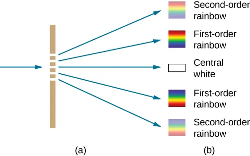
A transmission diffraction grating produces a central zero-order maximum and symmetrically placed higher-order spectra, illustrating how dispersion increases with order and enabling wavelength measurement from angular separation. Source.
This underpins many astronomical instruments, including spectrometers used to analyse stellar composition and motion.
Path Difference, Constructive Interference, and Angular Position
Constructive interference arises when the waves from adjacent slits have a path difference equal to a whole number of wavelengths. At these angles, the individual wavefronts reinforce each other to create a bright maximum. This leads directly to the key diffraction grating condition expressed in the OCR specification.
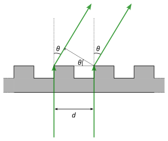
A transmission grating’s geometry shows adjacent slits separated by d producing rays that emerge at angle θ and meet the constructive-interference condition d sinθ = nλ, forming maxima used for precise wavelength determination. Source.
EQUATION
—-----------------------------------------------------------------
Diffraction Grating Equation (d sinθ = nλ) = d sinθ = nλ
d = Grating spacing (m)
θ = Angle of diffraction at a maximum (radians or degrees)
n = Order of the diffraction maximum (integer, unitless)
λ = Wavelength of light (m)
—-----------------------------------------------------------------
This equation is central to practical wavelength measurement. A student using a transmission grating can measure the angle θ for a clearly identifiable maximum, such as a coloured spectral line, and then calculate λ if d and n are known. Alternatively, if λ is known, the grating spacing d can be determined. This relationship is applicable only to maxima because these are locations of perfect constructive interference.
Transmission Gratings in Astronomical Observation
In astrophysics, transmission gratings help separate the light from distant stars and galaxies into component wavelengths. This is crucial because astronomers rely on spectral analysis to determine temperature, chemical composition, and radial velocity. The accuracy of these physical measurements depends on the precision with which wavelengths can be determined, making the diffraction grating equation a core tool.
Key Features of Transmission Gratings
Students should recognise the advantages of transmission gratings in astronomical instruments:
High spectral resolution due to many closely spaced slits.
Transmission geometry, which often allows efficient collection and analysis of faint starlight.
Sharp maxima, improving accuracy in locating angular positions.
Linear dispersion, which helps spread out wavelengths in a predictable manner.
The effectiveness of a transmission grating depends largely on the grating spacing d. A smaller d (more lines per millimetre) creates a larger separation between maxima for a given wavelength, improving the ability to distinguish fine spectral details.
Orders of Diffraction and Practical Implications
Diffraction maxima appear at different orders, labelled by the integer n in the diffraction grating equation. The zero-order maximum (n = 0) corresponds to direct transmission with no dispersion and therefore carries no wavelength information. Higher orders (n = 1, 2, 3, …) provide increasingly dispersed spectra but at potentially lower brightness, which is an important point for observing faint astronomical sources.
Diffraction order: The integer value n indicating the number of whole wavelengths by which paths differ at a constructive interference maximum.
The intensity of maxima typically decreases with increasing order because fewer photons contribute coherently at larger angles. Nonetheless, higher orders enhance spectral detail by spreading wavelengths further apart. Selecting an appropriate order is therefore a balance between brightness and resolution.
A further constraint comes from the term sinθ in the diffraction equation. Since sinθ cannot exceed 1, only orders satisfying nλ ≤ d can exist. This limits the maximum usable order for a given wavelength, particularly in ultraviolet or infrared observation.
Measuring Wavelength Using a Transmission Grating
Accurate measurement requires careful experimental method. Although specific procedures and calculations are excluded here, students should understand the conceptual steps involved:
Aligning the grating perpendicular to incident light.
Identifying bright maxima at equal angles on either side of the central beam.
Measuring θ precisely, often using optical benches or angular scales.
Applying the grating equation with known d and chosen n.
These steps illustrate the practical connection between theory and observation. High angular accuracy is crucial because small uncertainties in θ propagate to uncertainties in wavelength. Astronomical instruments therefore use precision gratings and sensitive detectors to ensure reliable spectra.
Factors Affecting Accuracy and Resolution
A variety of physical and instrumental factors influence the sharpness of maxima and the clarity of spectra:
Number of slits illuminated: More illuminated slits produce sharper maxima.
Uniformity of slit spacing: Imperfections broaden peaks and reduce resolution.
Wavelength range: Higher orders may overlap if the spectrum extends broadly in wavelength.
Angle of diffraction: Large angles can distort spectral lines if the geometry is not carefully controlled.
Understanding these factors helps students appreciate why diffraction gratings are engineered with high precision for professional astronomical use.
Practice Questions
Question 1 (2 marks)
A student uses a transmission diffraction grating to determine the wavelength of a spectral line. Explain why bright maxima occur at specific angles when light passes through the grating.
Mark scheme:
• Light from each slit interferes constructively at certain angles. (1)
• Constructive interference occurs when the path difference between adjacent slits is an integer multiple of the wavelength, producing a bright maximum. (1)
Question 2 (5 marks)
A transmission diffraction grating has 600 lines per millimetre. Monochromatic light is incident normally on the grating and the first-order maximum is observed at an angle of 22 degrees.
(a) Show how the diffraction grating equation is used to determine the wavelength of light.
(b) Explain how using a grating with more lines per millimetre would affect the measurement of the angle and the accuracy of the wavelength determined.
Mark scheme:
(a)
• States the diffraction grating equation d sinθ = nλ. (1)
• Correctly identifies that d is the slit spacing and relates it to the line density. (1)
• Shows that substituting d, n, and θ into the equation allows λ to be calculated. (1)
(b)
• More lines per millimetre means smaller slit spacing d, giving maxima at larger angles. (1)
• Larger angular separation increases precision in measuring θ, improving accuracy of the calculated wavelength. (1)
FAQ
Increasing the number of illuminated slits produces narrower and more intense maxima because more wavefronts add coherently at each constructive interference angle.
The minima between maxima become much darker, improving contrast in the interference pattern.
This enhanced sharpness is why high-quality astronomical gratings are designed to illuminate as many slits as possible.
Each order spreads wavelengths further apart, but higher orders also occupy larger angular ranges.
If the light source contains a wide range of wavelengths, shorter wavelengths of one order can appear at the same angle as longer wavelengths of a higher order.
This overlap can cause misidentification of spectral lines, so instruments often use filters or limit detection to certain orders.
The condition sinθ must be less than or equal to 1, so only orders satisfying nλ ≤ d can exist.
This means a grating with smaller spacing (more lines per millimetre) supports fewer orders for the same wavelength range.
In practice, detectors also limit high orders because light intensity decreases significantly at larger angles.
Normal incidence ensures that the incoming wavefronts reach all slits simultaneously, keeping the path difference simple and directly dependent on d sinθ.
If the light were not incident normally, additional geometry would need to be considered, introducing an offset that complicates wavelength determination.
Normal incidence therefore reduces systematic errors and simplifies analysis for practical laboratory work.
Diffraction gratings provide linear dispersion: equal changes in wavelength produce equal changes in diffraction angle.
Prisms exhibit nonlinear dispersion because their refractive index varies with wavelength, meaning red and blue light spread unevenly.
For high precision:
Gratings separate wavelengths more uniformly.
They offer higher resolution when many slits are illuminated.
They minimise chromatic distortions present in prisms.
