
OCR Specification focus:
‘For capacitors in series: 1/C = 1/C1 + 1/C2 + … ; explain effect on total capacitance.’
This section explores how capacitors behave when connected in series, focusing on how charge, potential difference, and effective capacitance combine across the network. Understanding these ideas is essential for predicting circuit behaviour in both theoretical and practical contexts.
Introduction to Series Capacitor Arrangements
When capacitors are connected in series, they form a single pathway for charge, creating a configuration in which each capacitor influences the overall electrical behaviour of the circuit. A series arrangement is characterised by the same charge passing through every capacitor, while the potential differences across them combine to give the total p.d. across the network.
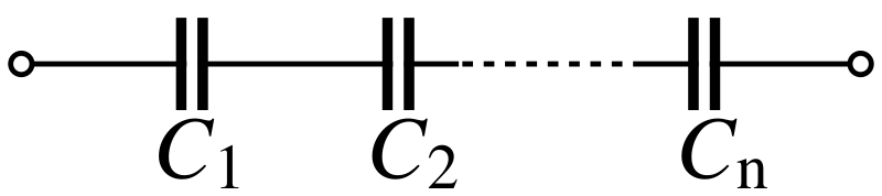
This diagram shows capacitors C1,C2,…,CnC_1, C_2, …, C_nC1,C2,…,Cn connected in series, illustrating the single conducting path through which the same charge must pass. It highlights how potential differences across each capacitor combine to form the total voltage across the series arrangement. The simple symbolic layout reinforces the fundamental structure of series capacitor networks. Source.
This arrangement is widely used to achieve specific capacitance values, to spread voltage across multiple components, and to operate safely at higher voltages than a single capacitor may tolerate.
Fundamental Behaviour of Capacitors in Series
In a series circuit, capacitors interact in a distinctive way because of the movement and distribution of charge. Although each capacitor may have a different capacitance value, the flow of charge is constrained to be identical on every plate pair within the network. This consistent charge behaviour is key to understanding how the total capacitance emerges from the combination of individual components.
Capacitance: The ability of a component to store electrical charge per unit potential difference.
When considering a set of capacitors in series, the total potential difference across the combination is the algebraic sum of the individual voltages across each capacitor. This characteristic distinguishes series configurations from parallel ones, in which potential difference is equal across all components.
Charge Distribution in Series
The charge stored on each capacitor in a series arrangement is equal. This arises because electrons removed from one plate must be supplied to the next, creating a chain of charge displacement along the connected plates. As a result, even if the individual capacitances differ, the magnitude of charge stored on every capacitor remains the same.
Key points about charge in series capacitors include:
• Identical charge magnitude on all capacitors.
• Charge transfer occurs sequentially through the circuit.
• The same current flows through each capacitor during charging or discharging.
A direct implication is that capacitors with smaller capacitance experience larger potential differences, because for a fixed quantity of charge, potential difference increases as capacitance decreases.
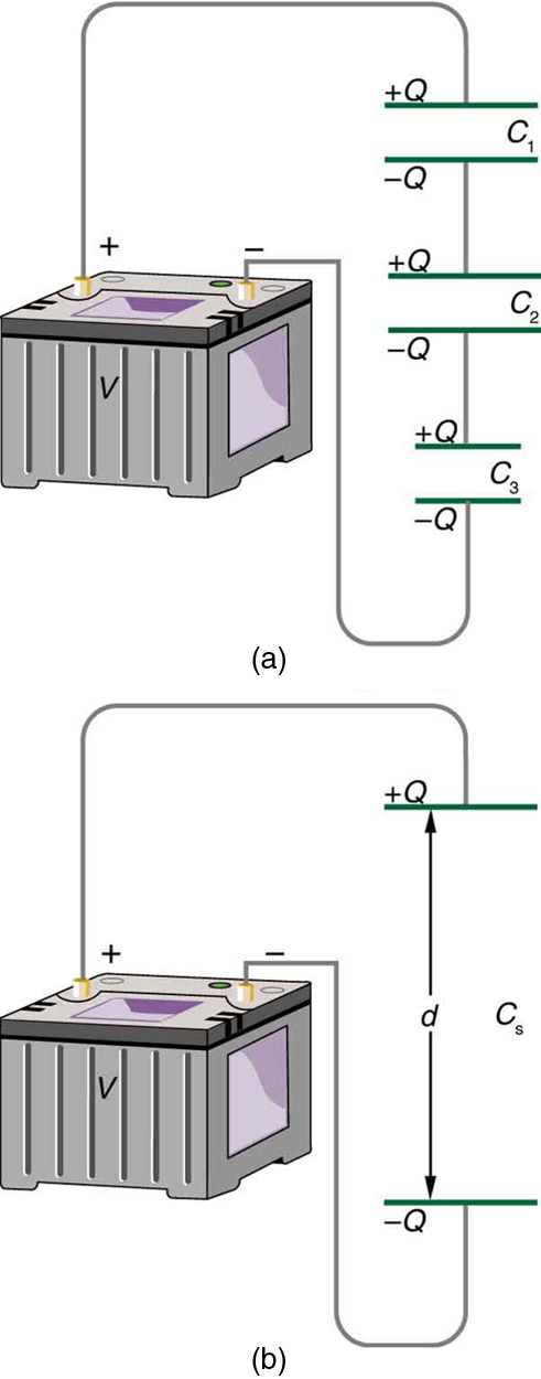
This image depicts three capacitors in series, each carrying equal and opposite charges, and an equivalent single capacitor representing the combined effect. The lower diagram shows how the effective plate separation increases, reducing total capacitance. Additional contextual detail such as the battery symbol and explicit spacing supports a deeper physical understanding while remaining consistent with syllabus requirements. Source.
Deriving the Effective Capacitance in Series
To analyse the combined effect of capacitors in a series arrangement, we apply a key mathematical relationship used throughout A-Level Physics.
EQUATION
—-----------------------------------------------------------------
Series Capacitance (C_total) = 1 / (1/C1 + 1/C2 + …)
C_total = Total capacitance of the series combination, measured in farads (F)
C1, C2, … = Capacitances of individual capacitors, measured in farads (F)
—-----------------------------------------------------------------
This equation indicates that the reciprocal of the total capacitance is equal to the sum of the reciprocals of the individual capacitances. A normal sentence is needed here to continue explaining the conceptual implications of this mathematical form.
The form of the series capacitance expression means the total capacitance is always less than the smallest individual capacitor in the series. This occurs because adding capacitors in series effectively increases the separation between the effective plates of the system, reducing its overall ability to store charge for a given potential difference.
Physical Interpretation and Circuit Implications
The reduction in capacitance produced by a series combination has several electrical and practical consequences that students must understand clearly.
Impact on Potential Difference
Since the total potential difference is divided between capacitors in series:
• Capacitors with lower capacitance take a higher share of the total voltage.
• The division of voltage is inversely proportional to capacitance.
• Careful selection is required to prevent overvoltage damage in sensitive capacitors.
Because charge is identical across all capacitors, and because potential difference is related to charge by Q = C V, the capacitor with the smallest capacitance experiences the largest voltage. Engineers often use this principle deliberately to distribute voltage stresses across several components.
Practical Reasons for Using Capacitors in Series
Series combinations are employed in real circuits for several beneficial reasons:
• Increasing maximum working voltage, allowing the combination to withstand higher p.d. than a single capacitor.
• Adjusting overall capacitance to achieve a desired low value not readily available as a single component.
• Balancing energy distribution across multiple components under varying electrical loads.
• Ensuring safety in circuits where voltage spikes may occur.
While a series combination reduces capacitance, the gain in voltage tolerance is essential in high-voltage power supplies, pulse circuits, and certain filtering applications.
Techniques for Analysing Series Capacitor Networks
To solve problems and analyse circuits involving capacitors in series, students should be comfortable with a number of systematic steps:
• Identify all capacitors connected sequentially without branching paths.
• Calculate reciprocal capacitances and derive the effective value.
• Determine individual voltages using V = Q/C when total charge is known.
• Consider voltage-rating limits for each capacitor to assess safety.
• Combine this understanding with Kirchhoff’s laws when capacitors are embedded in larger circuits.
This structured approach ensures clarity when predicting how energy, charge, and potential difference behave in series networks.
Summary of Key Characteristics of Series Capacitors
Although these notes do not provide a conclusion, it is essential to highlight key operational features for clarity:
• Charge is the same on all capacitors.
• Potential differences add to produce the total voltage.
• Total capacitance decreases and is always less than the smallest individual capacitor.
• The series formula must be used to calculate C_total accurately.
Practice Questions
Question 1 (2 marks)
Two capacitors, C1 = 4.0 microfarads and C2 = 6.0 microfarads, are connected in series.
State the expression used to calculate the total capacitance of capacitors in series, and determine whether the total capacitance will be greater than, equal to, or less than the smallest individual capacitor.
Question 1 (2 marks)
• States correct expression for series capacitance: 1/C = 1/C1 + 1/C2 (+1 mark).
• States that total capacitance is less than the smallest capacitor (+1 mark).
Question 2 (5 marks)
A student connects three capacitors of values 2.0 microfarads, 3.0 microfarads, and 12.0 microfarads in series across a power supply.
(a) Explain why the charge stored on each capacitor is the same.
(b) Using appropriate reasoning, describe how the potential difference is shared among the capacitors.
(c) State one practical reason why capacitors may deliberately be connected in series in a real circuit.
Question 2 (5 marks)
(a)
• Charge is the same because the same current flows through all components in a series circuit (+1 mark).
• Electrons removed from one plate must be deposited on the next, leading to identical charge magnitudes on all capacitors (+1 mark).
(b)
• Potential difference across capacitors in series adds to give the total p.d. (+1 mark).
• The capacitor with the smallest capacitance takes the largest share of voltage (+1 mark).
• Explanation that V = Q / C so, with constant Q, lower capacitance results in higher voltage (+1 mark).
(c)
• Any valid reason, e.g. to increase maximum working voltage, to obtain a smaller effective capacitance value, or to distribute voltage across components (+1 mark, max 1 mark for this part).
FAQ
Adding capacitors in series effectively increases the total distance between the plates of the equivalent capacitor. A larger separation reduces the ability of the system to store charge per unit potential difference.
Each capacitor introduces another layer of insulation between charge-storing surfaces, so the overall electric field must span a greater distance. This lowers the equivalent capacitance even further as more components are added.
Yes. Real capacitors have manufacturing tolerances, meaning their true capacitances may be slightly above or below the labelled value.
In a series chain:
• A capacitor with lower-than-expected capacitance will take a larger potential difference than predicted.
• This can risk exceeding its voltage rating, potentially leading to failure.
• Engineers sometimes add voltage-balancing resistors across series capacitors to manage this effect.
Leakage current is the small, unintended current that flows through real dielectric materials. In series capacitors, unequal leakage currents can cause the voltage distribution to drift over time.
This may result in:
• One capacitor taking a larger share of the total voltage
• Reduced reliability in long-term DC applications
• The need for balancing resistors to maintain stable voltage division
Series connecting standard capacitors may offer advantages when a suitable single component is unavailable or impractical.
Benefits include:
• Achieving a specific low capacitance value using readily available components
• Allowing the combination to operate at higher voltages
• Improving thermal distribution across multiple parts rather than concentrating stress on one device
These reasons can make series networks more flexible than sourcing a specialised capacitor.
The energy stored in each capacitor depends on the voltage across it, and in series the voltage is divided unevenly according to capacitance. Smaller capacitors store proportionally more energy because they take a higher potential difference.
However, the total energy stored by the whole series combination is usually less than the energy that could be stored by a single capacitor of the same physical size operating at its rated voltage, due to the reduced equivalent capacitance.
