
OCR Specification focus:
‘Analyse circuits containing capacitors, including resistors, using appropriate circuit laws and relationships.’
Analysing Circuits with Capacitors and Resistors
A capacitor–resistor circuit behaves differently from one containing only resistors, due to the ability of a capacitor to store charge and oppose changes in voltage. Understanding how these components interact allows the prediction of current and potential-difference behaviour during any circuit operation.
Understanding the Roles of Capacitors and Resistors
A capacitor is an electrical component designed to store charge on two conductive plates separated by an insulator. A resistor restricts current and controls the rate at which a capacitor charges or discharges in a circuit.
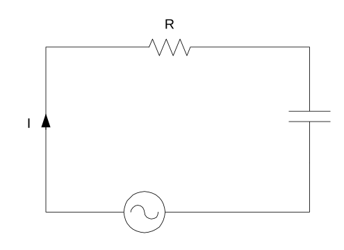
Simple RC circuit diagram illustrating how a voltage source drives current through a resistor and then into a capacitor. The layout highlights the shared current and the distinct potential differences across each component. The source symbol is drawn generically but can be interpreted as a DC supply for this topic. Source.
Together, they form the basis of transient circuit analysis, where electrical conditions change with time rather than remain steady.
Capacitor: A component that stores electrical charge on two separated plates when connected across a potential difference.
In combined circuits, capacitors influence the voltage across components, while resistors determine how quickly that voltage changes. The resulting interactions must be analysed using appropriate circuit laws such as Kirchhoff’s laws, the capacitor charge–voltage relationship, and standard rules for series and parallel arrangements.
Key Circuit Laws and Relationships
When analysing any circuit containing capacitors and resistors, several fundamental laws apply:
Kirchhoff’s Current Law (KCL): The total current entering a junction equals the total current leaving it.
Kirchhoff’s Voltage Law (KVL): The sum of potential differences around any closed loop is zero.
Ohm’s Law: The potential difference across a resistor is proportional to the current through it.
These principles allow systematic evaluation of current pathways and potential differences in mixed component networks.
EQUATION
—-----------------------------------------------------------------
Capacitor Charge–Voltage Relationship (Q = CV)
Q = Charge stored on the capacitor (coulomb)
C = Capacitance of the capacitor (farad)
V = Potential difference across the capacitor (volt)
—-----------------------------------------------------------------
This relationship is essential when predicting how the voltage across a capacitor varies as it charges or releases energy through a resistor.
A single sentence is required here to maintain spacing between structured blocks, clarifying how the equation forms the foundation for further circuit analysis.
Using Series and Parallel Concepts in Mixed Circuits
Capacitors and resistors can appear in various combinations, and their arrangement influences both total resistance and effective capacitance.
Series arrangements
The same charge passes through each capacitor because they carry identical current at any instant.
The total potential difference is the sum of the voltages across each capacitor.
Resistors in series share the supply voltage in proportion to their resistances.
Parallel arrangements
Capacitors share the same potential difference.
Total charge divides between branches.
Resistors in parallel divide current while maintaining the same voltage across each branch.
These structural rules are vital before analysing dynamic behaviour such as charging and discharging.
Charging Behaviour in Capacitor–Resistor Circuits
When a capacitor is connected to a supply through a resistor, electrons flow onto one plate while being removed from the other until the capacitor reaches the supply potential difference. The resistor regulates this flow by limiting current. Students should understand the qualitative pattern of this behaviour:
At the start, the capacitor has zero potential difference, so the current is maximum.
As charge accumulates, the potential difference across the capacitor rises, reducing current.
Eventually, current approaches zero when the capacitor becomes fully charged.
During charging, both the resistor voltage and capacitor voltage must be analysed simultaneously.
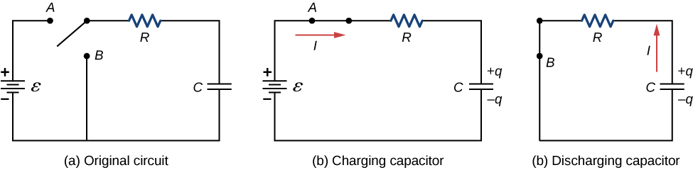
Three-part RC circuit diagram showing the original loop, the charging path with a DC source driving current through R into C, and the discharging path where the capacitor releases stored charge through the resistor. The panels visually distinguish how the switch position changes the loop analysed using Kirchhoff’s laws. No additional mathematical content beyond this subtopic’s requirements is included. Source.
Discharging Behaviour in Capacitor–Resistor Circuits
A discharging capacitor releases stored charge through a resistor. As electrons redistribute, the potential difference across the capacitor falls continuously. Important characteristics include:
Maximum current occurs at the start of discharge.
Current and voltage decrease over time due to falling stored charge.
Energy is dissipated in the resistor as thermal energy.
Students should interpret changing values by applying KVL around the loop, recognising that the capacitor’s decreasing potential difference directly drives the diminishing current.
Practical Steps for Analysing Mixed Circuits
To analyse any combination of capacitors and resistors, adopt a structured approach:
Step-by-step method
Identify component arrangement: Determine whether capacitors or resistors are in series or parallel.
Calculate effective capacitance or resistance: Use the appropriate combination rules before any time-dependent analysis.
Apply Kirchhoff’s laws: Write loop or junction equations to relate component voltages and currents.
Use the charge–voltage relationship: Substitute Q = CV where required to connect potential difference with stored charge.
Consider initial and final conditions: Recognise that transents govern behaviour when switches open or close.
Track how values change with time: Understand that current, voltage, and charge vary continuously during charging or discharging.
Each of these steps allows precise prediction of time-varying circuit behaviour in accordance with the OCR specification’s requirements.
Interpreting Measurements in Capacitor–Resistor Circuits
Students frequently encounter circuits where meters track voltage or current changes. Analysing these readings requires conceptual clarity:
Ammeter readings show how current falls as the capacitor charges or rises momentarily as it discharges.
Voltmeter readings reveal how the potential difference across the capacitor increases or decreases relative to the supply or across the resistor.
Recognising the relationship between meter readings and theoretical predictions reinforces understanding of transient circuit behaviour.
Representation of Capacitor–Resistor Circuits
Circuit diagrams help visualise how capacitors and resistors interact:
Charging circuits show a supply connected in series with a resistor and capacitor.
Discharging circuits show only the resistor and capacitor loop after the supply is removed.
Branching circuits include parallel pathways for current distribution, requiring careful application of KCL.
By combining circuit diagrams with analytical techniques, students can fully interpret mixed electrical systems containing capacitors and resistors.
Practice Questions
Question 1 (2 marks)
A capacitor is connected in series with a resistor and a DC power supply. Explain why the current in the circuit decreases as the capacitor charges.
Question 1 (2 marks)
• As the capacitor charges, its potential difference increases (1)
• This reduces the potential difference across the resistor, causing the current to decrease (1)
Question 2 (5 marks)
A circuit contains a resistor R and a capacitor C connected in series with a DC supply. The switch is closed at time t = 0.
(a) Describe how the potential difference across the resistor and across the capacitor change during the charging process.
(b) Using appropriate circuit laws and relationships, explain how these changes allow you to analyse the behaviour of the circuit during the charging period.
Question 2 (5 marks)
(a)
• At t = 0, the potential difference across the capacitor is zero and across the resistor is equal to the supply voltage (1)
• As time progresses, the potential difference across the capacitor increases (1)
• The potential difference across the resistor decreases correspondingly (1)
(b)
• Use of Kirchhoff’s voltage law: supply voltage = voltage across resistor + voltage across capacitor (1)
• Use of Q = CV or the idea that increasing capacitor voltage reduces current, allowing prediction of how current, charge, and potential difference change over time (1)
FAQ
Internal resistance acts like an additional resistor in series, reducing the initial charging current and altering voltage distribution within the loop.
It lowers the effective supply voltage available to the external resistor and capacitor, meaning the capacitor charges more slowly than predicted by ideal-circuit assumptions.
When analysing the circuit, the total series resistance should be treated as R + r, where r is the internal resistance.
During charging, current flows to accumulate charge on the capacitor plates. When the supply is removed and a discharge path is provided, the stored charge becomes the driving source.
The capacitor’s potential difference pushes current in the opposite direction to the original charging current.
This reversal is essential when applying Kirchhoff’s voltage law, as the sign of the capacitor’s voltage term changes during discharge.
Only the resistor(s) in the direct charging path influence the charging current.
To identify them:
• Trace the loop that includes both the capacitor and the power supply.
• Include all resistors through which charging current must pass.
• Exclude resistors in branches that do not carry charging current.
The effective resistance of this path determines how quickly the capacitor charges.
In steady state, a capacitor behaves as an open circuit because no current flows through a fully charged capacitor under DC conditions.
When inserted into an active DC circuit:
• The voltage across nearby components may momentarily shift as the capacitor begins to charge.
• The capacitor initially draws current, disturbing the established distribution.
• The system settles into a new steady state once the capacitor charges.
This transient must be analysed using the same laws applied to any RC charging event.
Kirchhoff’s current and voltage laws act as consistency checks.
Useful diagnostic steps include:
• Verifying that all currents entering and leaving a junction are accounted for.
• Ensuring that the sum of voltage rises and drops around every loop equals zero.
• Checking that capacitor voltage changes are physically reasonable (for example, never exceeding the supply voltage during charging).
• Confirming that resistor voltage drops correspond to currents predicted for that stage of charge or discharge.
These checks help reveal incorrect assumptions, mislabelled components, or impossible voltage relationships.
