
OCR Specification focus:
‘Relate C = ɛ0A/d and C = ɛrɛ0A/d for a parallel-plate capacitor; define permittivity and relative permittivity.’
A parallel-plate capacitor provides a uniform electric field between two conducting plates, allowing charge storage governed by geometry and material properties, especially the behaviour of permittivity.
Parallel-Plate Capacitors: Core Structure and Purpose
A parallel-plate capacitor consists of two large, flat, conductive plates placed close together and separated by either a vacuum, air, or a dielectric material. The capacitor stores energy by maintaining equal and opposite charges on the plates, producing a uniform electric field between them.
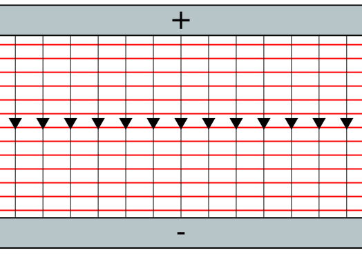
Uniform electric field between parallel plates with straight, evenly spaced field lines and perpendicular equipotentials. This visual emphasises the geometric basis of field uniformity used in capacitor modelling. No extra information beyond the syllabus requirement is included. Source.
This arrangement makes the parallel-plate capacitor one of the most analytically useful capacitor models because the electric field and charge distribution are simple and predictable.
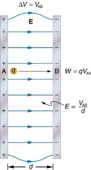
Parallel conducting plates labelled to illustrate the uniform electric field and the relationship E=V/dE = V/dE=V/d. Slight fringing is shown at the edges, but the central region reflects the uniform-field assumption used in capacitor theory. Extra details such as work annotations appear but do not affect the core syllabus content. Source.
When connected to a power supply, the capacitor charges as electrons move onto one plate and away from the other, establishing a potential difference. The ability of the capacitor to store charge per unit potential difference is its capacitance, a central measurable quantity that depends directly on geometry and permittivity.
Capacitance and Geometric Dependence
The capacitance of a parallel-plate capacitor depends on the area of overlap of the plates and the distance between them. A larger plate area allows more charge to accumulate, while a larger separation distance reduces the electric field strength for a given potential difference and therefore reduces capacitance. These geometric factors make parallel-plate capacitors valuable in experimental setups where predictable and tunable electric fields are required.
The simplest form of the capacitance equation applies when the region between the plates is a vacuum. This highlights the fundamental role of vacuum permittivity, a constant describing how electric fields permeate free space.
EQUATION
—-----------------------------------------------------------------
Capacitance in Vacuum (C) = ɛ₀A / d
C = Capacitance in farads (F)
ɛ₀ = Vacuum permittivity (8.85 × 10⁻¹² F m⁻¹)
A = Plate overlap area (m²)
d = Separation between plates (m)
—-----------------------------------------------------------------
This relationship shows that capacitance increases with larger plate area and decreases with greater plate separation. Although simple, this expression underpins the more general case involving dielectric materials.
Permittivity: A Material’s Response to Electric Fields
The concept of permittivity is essential for understanding how materials modify electric fields. When a dielectric—an insulating material—is inserted between the plates, it becomes polarised by the electric field. This polarisation reduces the effective field between the plates for the same charge, allowing the capacitor to store more charge at the same potential difference.
Permittivity: A measure of how easily a material allows electric field lines to pass through it, affecting how the material responds to electric fields.
The introduction of a dielectric therefore increases the capacitance of the capacitor by reducing the electric field strength between the plates.
After a dielectric is introduced, the permittivity of the material replaces vacuum permittivity in the capacitance formula.
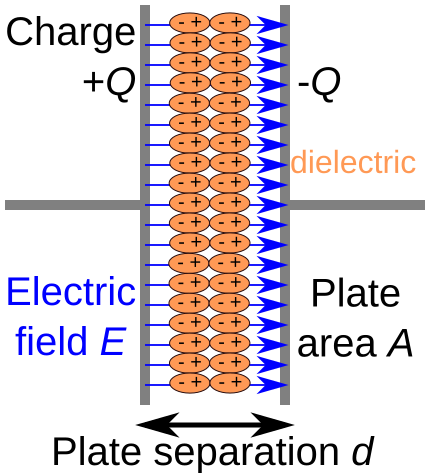
Schematic of a parallel-plate capacitor containing a dielectric. The plates have area A and are separated by distance d, while the dielectric polarises and reduces the internal field E, increasing capacitance. All labels match variables used in the OCR formulae C=ε0A/dC = \varepsilon_0A/dC=ε0A/d and C=εrε0A/dC = \varepsilon_r\varepsilon_0A/dC=εrε0A/d. Source.
This leads to a modified expression involving relative permittivity.
Relative Permittivity and Its Physical Significance
Relative permittivity compares the permittivity of a material with that of a vacuum and indicates how much a material increases capacitance relative to empty space.
Relative Permittivity (ɛᵣ): The ratio of a material’s permittivity to the vacuum permittivity, indicating how strongly the material affects electric fields compared with free space.
Materials with higher relative permittivity polarise more strongly, reducing the internal electric field more and providing a larger increase in capacitance. This makes dielectric selection critical in capacitor design, especially in high-performance electronic components.
A dielectric-filled capacitor follows an extended capacitance equation incorporating both ɛ₀ and ɛᵣ.
EQUATION
—-----------------------------------------------------------------
Capacitance with Dielectric (C) = ɛᵣɛ₀A / d
C = Capacitance in farads (F)
ɛᵣ = Relative permittivity (dimensionless)
ɛ₀ = Vacuum permittivity (F m⁻¹)
A = Plate overlap area (m²)
d = Separation between plates (m)
—-----------------------------------------------------------------
Inserting a dielectric can multiply the capacitance by a factor equal to the relative permittivity. This enhancement makes dielectrics fundamental in practical capacitor applications, from smoothing circuits to timing systems.
Visualising the Effect of Dielectrics
When discussing permittivity, it is useful to consider how the electric field behaves inside materials. Important features include:
Polarisation of dielectric molecules, which align with the electric field.
Reduction in the effective field, because the dielectric’s internal field opposes the applied field.
Increased charge storage, because a weaker electric field permits greater accumulation of charge for the same applied potential difference.
These effects illustrate why dielectrics are carefully chosen in engineering contexts, where material properties must optimise the balance between size, voltage rating, and capacitance.
Practical Design Considerations
To understand how capacitor performance is influenced by design choices, students should note the following dependencies:
Plate area (A)
Increasing A increases the region available for charge storage.
Larger A gives proportionally greater capacitance.
Plate separation (d)
Smaller d yields a stronger electric field for a given potential difference.
Decreasing d increases capacitance but may raise the risk of electrical breakdown.
Dielectric properties (ɛᵣ)
Higher relative permittivity gives higher capacitance.
Dielectrics also determine breakdown voltage and influence energy density.
Understanding these relationships helps explain why parallel-plate capacitors remain foundational in physics education and a key model for analysing uniform electric fields.
Practice Questions
Question 1 (2 marks)
A parallel-plate capacitor has plate area A and separation d. Explain how inserting a dielectric with relative permittivity greater than 1 affects the capacitance of the capacitor.
Mark scheme:
• States that the capacitance increases when a dielectric is inserted. (1)
• Explains that the dielectric reduces the effective electric field inside the capacitor or allows more charge to be stored for the same potential difference. (1)
Question 2 (5 marks)
A student investigates how the capacitance of a parallel-plate capacitor depends on the geometry of its plates and the material placed between them.
(a) State the equation for the capacitance of a parallel-plate capacitor filled with a dielectric.
(b) Describe how each variable in the equation influences the capacitance.
(c) The student replaces the dielectric with another material of higher relative permittivity but keeps A and d constant. Explain, in terms of electric fields and material behaviour, why the capacitance increases.
Mark scheme:
(a) States C = epsilon_r epsilon_0 A / d. (1)
(b)
• Increasing plate area A increases capacitance because more charge can be stored. (1)
• Increasing separation d decreases capacitance because the electric field is weaker for a given potential difference. (1)
• Increasing relative permittivity epsilon_r increases capacitance because the dielectric becomes more polarised or reduces the effective internal electric field. (1)
(c)
• Explains that a dielectric with higher relative permittivity polarises more strongly in the presence of the electric field. (1)
• States that this reduces the effective electric field between the plates, allowing more charge to be stored for the same potential difference, hence increasing capacitance. (1)
FAQ
A dielectric contains bound charges that cannot move freely like those in a conductor, but they can shift slightly when exposed to an electric field.
This shift creates molecular dipoles that align with the field. Their internal opposing field partially cancels the external field between the plates.
As a result:
• The effective electric field decreases
• A greater charge can be stored for the same applied potential difference
Relative permittivity depends on how easily atoms or molecules become polarised. Materials with more polarisable electron clouds or permanent dipoles typically have higher permittivity.
Factors include:
• Molecular shape and symmetry
• Bond type and electron density
• Ability of molecules to rotate or reorient in the field
Crystalline materials often show anisotropic permittivity, meaning it can vary with direction.
Although reducing d increases capacitance, practical constraints include:
• Risk of electrical breakdown: the electric field may ionise the dielectric, causing it to conduct.
• Mechanical stability: plates must remain rigid and parallel to maintain a uniform field.
• Manufacturing tolerances: ultra-thin gaps require precision fabrication to avoid short circuits or dielectric failure.
Different dielectric materials have different breakdown strengths, so the minimum safe separation varies.
Permittivity generally changes with temperature because molecular motion influences how easily dipoles align.
In many materials:
• Increasing temperature reduces alignment, decreasing relative permittivity.
• In polar dielectrics, thermal agitation opposes dipole orientation, lowering capacitance.
Some engineered dielectrics show controlled temperature dependence to stabilise capacitor performance in electronic circuits.
With a fixed voltage, increasing capacitance allows more charge to accumulate on the plates.
Work is done by the power supply to move this additional charge, increasing the stored energy.
U = 1/2 C V^2, so if V is constant, increasing C increases U.
Microscopically, energy is stored in the polarisation of the dielectric, as molecular dipoles shift and align with the field.
