
OCR Specification focus:
‘Define magnetic flux Φ = B A cosθ and magnetic flux linkage; state the weber as the unit.’
Magnetic flux and magnetic flux linkage describe how magnetic fields interact with areas and coils, forming essential foundations for electromagnetic induction, generator behaviour, and wider A-Level electromagnetism topics.
Magnetic Flux
Magnetic flux is the fundamental measure of how much magnetic field passes through a given area. Understanding this quantity allows students to describe, quantify, and compare induction effects in different physical systems.
Magnetic Flux: The product of magnetic flux density and the perpendicular area through which the field passes; it quantifies how much magnetic field penetrates a surface.
The concept is rooted in the idea that a magnetic field may be more or less “linked” with an area depending on its orientation. When the field is parallel to a surface, the amount of flux through it is effectively zero; when perpendicular, flux is maximised.
The Magnetic Flux Equation
Flux is calculated using a standard geometric relationship that helps determine how field direction affects flux through a surface.
EQUATION
—-----------------------------------------------------------------
Magnetic Flux (Φ) = B A cosθ
B = Magnetic flux density (tesla, T)
A = Area normal to the field (square metres, m²)
θ = Angle between the magnetic field direction and the normal to the surface (radians or degrees)
—-----------------------------------------------------------------
As the angle changes, the effective component of the area exposed to the field changes accordingly, making flux a directional quantity.
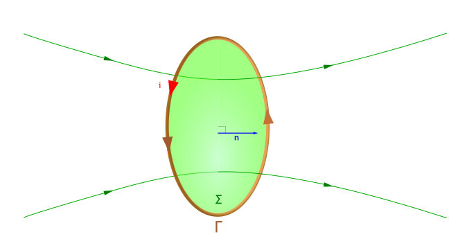
Magnetic field lines pass through a flat surface at an angle θ to the area’s normal, illustrating how the component of B perpendicular to the surface determines the magnetic flux Φ. The diagram labels the magnetic flux density B, the area A, and the angle θ, directly supporting the relationship Φ = B A cosθ. Any additional visual detail simply clarifies how flux depends on field direction and surface orientation. Source.
This dependency is vital for understanding how rotating coils in generators or transformers experience changing flux, leading to induced e.m.f.
The Unit of Magnetic Flux
The weber (Wb) is the SI unit for magnetic flux. It represents one tesla metre squared, consistent with the equation above. Students should be aware that the weber is often encountered in induction contexts, especially when dealing with time-varying fields.
Magnetic Flux Linkage
Magnetic flux linkage extends the concept of magnetic flux, allowing us to analyse physical systems with coils. A key reason flux linkage is used rather than basic flux is that most practical electromagnetic components employ multiple turns of wire, each of which interacts with the magnetic field.
Magnetic Flux Linkage: The product of the number of turns in a coil and the magnetic flux passing through a single turn.
Flux linkage is therefore represented as NΦ, where N is the number of turns.
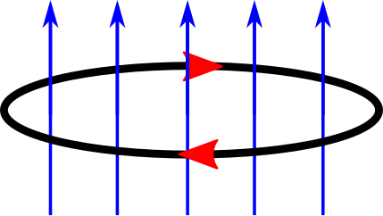
A single coil is shown with magnetic field lines and flux Φ passing through its interior, annotated to highlight the area and direction of the field. This provides a visual bridge between the concept of magnetic flux through one loop and magnetic flux linkage when many turns are used. Any additional symbols simply label the geometry and directions already described in the text. Source.
A simple sentence here helps highlight that flux linkage is the quantity used in Faraday’s law (covered in another section) because it captures how total field interaction changes when more turns of wire are present.
Factors Affecting Magnetic Flux and Flux Linkage
Several physical factors affect the magnitude of flux and flux linkage, making it crucial for students to understand how design choices influence performance in electromagnetic systems.
Magnetic Flux Density
The stronger the magnetic field, the greater the flux. Systems such as solenoids or permanent magnets rely on high magnetic flux density to maximise interaction with neighbouring conductors.
Area of the Coil or Surface
Increasing the area through which the field passes increases flux proportionally. In coil design, a wider loop or a more extended solenoid produces greater total flux linkage.
Orientation
The angle θ plays a large role. Flux is greatest when the field is perpendicular to the surface and least when parallel. Rotational devices depend heavily on varying θ to cause changing flux over time.
Number of Turns
In multi-turn coils, flux linkage increases directly with N.
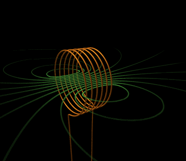
A long solenoid is depicted with dense, nearly uniform magnetic field lines inside and weaker field lines outside. This illustrates how each turn of the coil shares the same internal magnetic flux, so the total magnetic flux linkage NΦ grows with the number of turns. The diagram also hints at later electromagnetism ideas but is used here only to visualise flux in a multi-turn coil. Source.
Visualising Magnetic Flux
Students benefit from conceptualising magnetic flux in terms of magnetic field lines passing through a surface. Although flux is not literally counted by discrete lines, diagrams often use density of field lines to illustrate how much field interacts with a loop or conductor.
Useful visual interpretations include:
Dense field regions representing high flux density B.
Large surface areas intercepting more lines, showing greater flux Φ.
Tilting a coil relative to field lines to demonstrate the cosθ component.
Multiple loops accumulating more total field intersections, emphasising flux linkage.
These visual models support the mathematical relationships and help bridge the gap between abstract equations and physical behaviour.
Applications of Flux and Flux Linkage
Although this subsubtopic focuses on definitions and relationships, it is important to recognise that flux and flux linkage underpin many of the electromagnetic devices studied in later sections.
Examples of contexts where flux and flux linkage are essential include:
Understanding how changing flux leads to induced e.m.f.
Describing how coiled conductors amplify induction effects.
Explaining generator and alternator operation in terms of varying flux.
Interpreting transformer behaviour using flux linkage in coupled coils.
Each of these examples relies directly on the ideas developed in this subsubtopic. By mastering the definitions, units, and relationships for magnetic flux and magnetic flux linkage, students are equipped to engage with more advanced concepts within electromagnetism.
Practice Questions
Question 1 (2 marks)
A uniform magnetic field of flux density 0.40 T passes perpendicularly through a single flat coil of area 6.0 × 10⁻³ m².
Calculate the magnetic flux through the coil.
Question 1 (2 marks)
• Substitution into flux equation: Φ = B A. (1 mark)
• Correct numerical answer: Φ = 0.40 × 6.0 × 10⁻³ = 2.4 × 10⁻³ Wb. (1 mark)
Question 2 (5 marks)
A coil with 150 turns is placed in a magnetic field. The coil has an area of 2.5 × 10⁻³ m² and is initially oriented so that the plane of the coil is parallel to the magnetic field lines.
(a) State the expression for magnetic flux.
(b) Explain what is meant by magnetic flux linkage.
(c) The coil is then rotated so that its plane becomes perpendicular to the magnetic field lines, where the flux density is 0.80 T.
Calculate the magnetic flux linkage in this final position and discuss why the value changes as the orientation alters.
Question 2 (5 marks)
(a) States flux expression Φ = B A cosθ. (1 mark)
(b) Defines magnetic flux linkage as NΦ or the product of the number of turns and the flux through one coil. (1 mark)
(c) Substitution into flux linkage expression: NΦ = 150 × (0.80 × 2.5 × 10⁻³). (1 mark)
• Correct flux linkage value: 0.30 Wb. (1 mark)
• Discussion of orientation: flux depends on cosθ, so rotating the coil changes the effective area exposed to the field, increasing flux as it becomes perpendicular. (1 mark)
FAQ
Magnetic flux density describes the strength of the magnetic field at a point, while magnetic flux measures how much of that field passes through a given area.
In practice:
• Magnetic flux density tells you how strong a magnet or electromagnet is.
• Magnetic flux tells you how effectively that field interacts with a loop or area, which is essential for understanding induction.
Flux depends on both the field strength and geometry, making it the more useful quantity when analysing coils, surfaces, or rotating systems.
Magnetic flux depends on the component of the area that is perpendicular to the magnetic field. The perpendicular component is A cosθ, where θ is the angle between the area’s normal and the field direction.
Using sinθ would instead give the parallel component, which has no contribution to flux.
This definition ensures flux is maximised when the field is perpendicular to the surface and becomes zero when they are parallel.
A negative flux simply indicates direction relative to the chosen area normal, not a change in magnitude.
This becomes important when:
• Comparing flux through multiple coils.
• Determining whether flux is increasing or decreasing over time.
• Applying induction concepts where direction matters.
The sign convention helps maintain mathematical consistency in larger electromagnetic systems, even though flux itself is always a magnitude of magnetic field through an area.
For a uniform magnetic field, the shape of the coil does not affect the flux as long as the total area enclosed remains constant.
However, shape matters when:
• The magnetic field is non-uniform.
• Only part of the coil lies in a strong field region.
• The coil is designed for mechanical rotation, where shape influences torque and exposure time.
Circular coils are common because they maximise area for a given perimeter, improving efficiency in many electromagnetic devices.
Each turn intercepts the same magnetic flux; therefore, total flux linkage is simply the sum of flux from each turn.
This linear relationship assumes:
• All turns experience the same field strength.
• The coil is tightly wound so each turn encloses nearly identical area.
• The field does not vary significantly across the coil’s thickness.
In real devices with large or loosely wound coils, small deviations occur, but the linear model remains highly accurate for most A-Level contexts.
