
OCR Specification focus:
‘State Faraday’s law of electromagnetic induction and Lenz’s law; interpret their implications.’
Electromagnetic induction explains how changing magnetic environments create electrical effects. Understanding Faraday’s law and Lenz’s law provides essential insight into how induced e.m.f. arises and why induced currents oppose their cause.
Faraday’s Law of Electromagnetic Induction
Faraday’s law is the foundational principle describing how electric potentials arise from changing magnetic conditions. When a conductor or coil experiences a variation in magnetic flux, an induced e.m.f. appears across it.
Magnetic flux is introduced here because its rate of change governs induction.
Magnetic Flux: The product of magnetic flux density and area perpendicular to the field, representing the field passing through a surface.
Although flux itself belongs to a neighbouring sub-topic, its presence is essential for understanding Faraday’s statement. Faraday discovered that an induced e.m.f. is generated whenever the magnetic flux through a circuit changes, regardless of whether the field changes, the area changes, or the circuit moves.
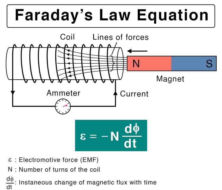
A diagram showing a bar magnet moving toward a coil, causing a changing magnetic flux that induces an e.m.f. ε = –N dφ/dt. The ammeter indicates the magnitude of the induced current, illustrating how flux change or increased coil turns raise the induced e.m.f. The brief printed notes beneath the equation only label the variables and add no syllabus-beyond detail. Source.
After identifying the role of flux, the statement of Faraday’s law must be given clearly.
Faraday’s Law: The magnitude of induced e.m.f. in a circuit is proportional to the rate of change of magnetic flux linkage through the circuit.
In practical terms, increasing the speed of motion, using stronger magnetic fields, or employing coils with more turns all increase the induced e.m.f. because they affect the rate at which flux linkage varies. This direct proportionality underpins the operation of many devices, including generators, transformers, and induction sensors.
To express the law mathematically, the relationship between induced e.m.f. and changing flux linkage appears in a standard form essential for OCR A-Level Physics learners.
EQUATION
—-----------------------------------------------------------------
Induced e.m.f. (𝓔) = − d(NΦ)/dt
𝓔 = Induced electromotive force, measured in volts (V)
N = Number of turns in the coil (dimensionless)
Φ = Magnetic flux through one turn, measured in webers (Wb)
t = Time, measured in seconds (s)
—-----------------------------------------------------------------
This mathematical form highlights that flux linkage, not flux alone, determines the induced e.m.f., and it also introduces the crucial negative sign, which directly leads to Lenz’s law.
Lenz’s Law and Its Physical Significance
Lenz’s law extends Faraday’s law by stating how the induced e.m.f. behaves directionally. Whereas Faraday’s law gives a magnitude, Lenz’s law provides the rule governing the direction of induced currents or voltages. The negative sign in the induction equation expresses precisely this idea: nature prevents changes to magnetic environments by producing opposing effects.
Lenz’s Law: The direction of any induced current or e.m.f. is such that the magnetic effect it creates opposes the change that produced it.
This principle ensures that electromagnetic induction complies with the conservation of energy. If induced currents did not oppose change, a system could spontaneously accelerate without the input of external work, contradicting fundamental physical laws.
Lenz’s law may be interpreted through several key observations:
A decreasing magnetic flux induces a current that attempts to maintain the original flux.
An increasing magnetic flux induces a current that tries to reduce the increase.
Motion of a conductor through a magnetic field always produces a force resisting the motion that caused the induction.
These ideas explain why pushing a magnet into a coil becomes more difficult when a current is induced, and why pulling it out similarly encounters resistance.
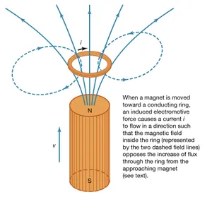
A diagram showing a conducting ring and a moving bar magnet, with the induced current producing a magnetic field opposing the increasing flux. The arrows indicate both the magnet’s velocity and the induced current direction, visually expressing the negative sign in Faraday’s law. The minimal printed caption restates Lenz’s law without adding non-syllabus material. Source.
Interpreting Faraday’s and Lenz’s Laws Together
When considered jointly, the two laws describe an elegant cause-and-effect relationship:
Faraday’s law states that changing flux → produces induced e.m.f.
Lenz’s law states that induced e.m.f. → produces an effect that opposes the original change.
This dual relationship can be visualised through the following structured ideas:
Key Implications
Induced e.m.f. depends on flux change
Faster changes produce greater induced voltages.
Systems with more coil turns experience higher flux linkage, elevating induced e.m.f.
Induced currents create magnetic fields
These fields act against the cause of induction.
The energy required to sustain or accelerate induction must come from external work.
Energy transfer is consistent across devices
Generators convert mechanical work into electrical energy through flux variation.
Transformers rely on alternating currents to ensure continuous flux change.
Conceptual Picture of Opposition
To conceptualise the opposing action described by Lenz’s law, it is helpful to view electromagnetic induction as a self-regulating phenomenon:
A system detects environmental change in flux.
An electrical response arises of exactly the magnitude predicted by Faraday’s law.
The direction of that response ensures that the system never amplifies the change but resists it, maintaining energy balance.
Practical Use in Analysis
When analysing induced e.m.f. in standard situations such as rotating coils, moving rods, or alternating magnetic fields, the following structured steps guide correct reasoning:
Identify the component of flux that is changing.
Determine the rate of change of flux linkage.
Apply Faraday’s law for magnitude.
Use Lenz’s law to determine direction, considering the magnetic effect of the induced current.
This systematic approach reflects the requirements of the OCR specification, ensuring that students can state both laws clearly and interpret their implications accurately in any induction scenario.
Practice Questions
Question 1 (2 marks)
A bar magnet is pushed steadily into a stationary coil connected to a sensitive voltmeter.
(a) State Faraday’s law of electromagnetic induction.
(b) Explain why the voltmeter reading briefly increases as the magnet enters the coil.
Question 1
(a)
• States that the induced e.m.f. is proportional to the rate of change of magnetic flux linkage. (1)
(b)
• Magnet entering the coil causes magnetic flux through the coil to change. (1)
• Changing flux induces an e.m.f., producing a momentary voltmeter reading. (1)
(Max 1 mark for part (b); total 2 marks)
Question 2 (5 marks)
A single-turn conducting loop rotates in a region of uniform magnetic field.
(a) Explain how the magnetic flux through the loop changes as it rotates.
(b) Using Faraday’s law, explain how and why an induced e.m.f. is produced in the loop.
(c) Apply Lenz’s law to describe the direction of the induced current at the moment when the plane of the loop is perpendicular to the magnetic field.
Question 2
(a)
• As the loop rotates, the angle between the magnetic field and the area of the loop changes. (1)
• Therefore the magnetic flux varies continuously from a maximum to zero and reverses. (1)
(b)
• A changing magnetic flux through the loop induces an e.m.f. according to Faraday’s law. (1)
• Greater rate of change of flux leads to larger induced e.m.f. (1)
(c)
• Lenz’s law: induced current produces a magnetic effect opposing the change causing it. (1)
• When the loop is perpendicular to the field, flux is changing most rapidly, so the current direction is such that its magnetic field opposes this rapid change. (1)
FAQ
A change in magnetic flux depends solely on how the field through a single loop varies, whereas a change in flux linkage also depends on the number of turns in the coil.
To distinguish them experimentally, compare measurements using coils with different numbers of turns:
If induced e.m.f. scales with the number of turns, flux linkage is changing.
If induced e.m.f. remains the same regardless of turns, only the flux through the region is changing.
This distinction helps identify whether the effect arises from field variation or coil geometry.
Induced e.m.f. requires a time-varying magnetic flux linkage. A strong field alone does not cause induction unless it changes with time or the coil moves or rotates.
Even if the magnetic field is large:
No change in the field
No change in coil orientation
No change in area
Therefore, no change in flux linkage occurs, and the e.m.f. remains zero.
Lenz’s law prevents induced currents from amplifying the change that produced them. Instead, they always oppose it.
This opposition means work must be done to maintain the change in flux:
Pushing a magnet into a coil requires extra force.
Moving a conductor out of a field slows unless work is supplied.
Energy transferred into these actions becomes electrical energy, ensuring overall energy conservation.
While area and number of turns are the primary factors, coil shape can influence how uniformly flux passes through the turns.
A coil with:
A compact, circular shape tends to intercept flux smoothly.
An elongated or irregular shape may experience non-uniform flux distribution.
Although overall flux linkage still follows Faraday’s law, the shape affects how effectively the geometry captures the field, slightly altering the induced e.m.f. in practical designs.
Yes. Lenz’s law alone provides a complete conceptual method for finding direction.
To use it:
Identify whether flux is increasing or decreasing.
Determine the direction of the magnetic field that would oppose that change.
The induced current must produce that opposing field.
This qualitative reasoning avoids the need for hand rules and works for any geometry, provided the direction of the changing flux is understood.
