
OCR Specification focus:
‘Use 𝓔 = − d(NΦ)/dt for induced e.m.f.; model changing flux situations.’
Induced e.m.f. and Rate of Change of Magnetic Flux
A changing magnetic environment creates an induced electromotive force (e.m.f.), forming the basis of electromagnetic induction. Understanding how magnetic flux varies with time is essential for analysing induced voltages.
The Concept of Magnetic Flux and Induced e.m.f.
The idea of magnetic flux is central to electromagnetic induction because it provides a measure of the magnetic field passing through a surface. When this flux changes, an induced e.m.f. arises in a conductor or coil, driving a current if a complete circuit is present.
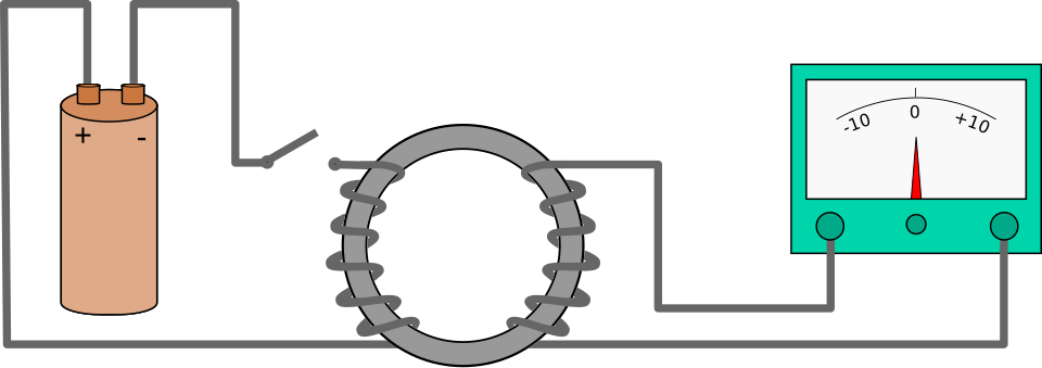
Faraday’s induction experiment: switching the current in the left-hand coil changes the magnetic flux in the iron ring, inducing an e.m.f. in the right-hand coil. The galvanometer shows a deflection only when the flux is changing, not when it is steady. This directly illustrates that induced e.m.f. depends on the rate of change of flux, not on the flux itself. Source.
Magnetic Flux: The product of magnetic flux density, area, and the cosine of the angle between field and normal; a measure of field passing through a surface.
This changing flux can occur through variations in magnetic field strength, changes in the orientation of the field, or alterations in the area exposed to the field. All these mechanisms influence the induced voltage experienced by a conductor.
Faraday’s Law and the Rate of Change of Flux Linkage
Faraday’s law provides the essential quantitative relationship describing induction by showing how the induced e.m.f. depends on how quickly the magnetic flux linkage changes. Flux linkage is the product of the number of turns of a coil and the magnetic flux through each turn. When either term varies over time, the e.m.f. changes accordingly.
A coil with many turns will experience a larger induced e.m.f. for the same rate of flux change, making coils a practical method to amplify induced voltages. This is why search coils, generator coils, and transformer windings rely on large numbers of tightly wound loops.
EQUATION
—-----------------------------------------------------------------
Induced e.m.f. (𝓔) = − d(NΦ)/dt
𝓔 = Induced electromotive force, measured in volts (V)
N = Number of turns in the coil (dimensionless)
Φ = Magnetic flux through one turn, measured in webers (Wb)
t = Time, measured in seconds (s)
—-----------------------------------------------------------------
The negative sign represents Lenz’s law, indicating that the induced e.m.f. opposes the change causing it. However, in many practical modelling situations at A-Level, the magnitude of the e.m.f. is the primary focus.
Understanding the Physical Meaning of d(NΦ)/dt
The rate of change of flux linkage describes how rapidly the magnetic environment seen by the coil turns is shifting. Several factors can bring about this change:
Changing magnetic flux density
Increasing or decreasing the magnetic field strength modifies Φ and therefore NΦ.
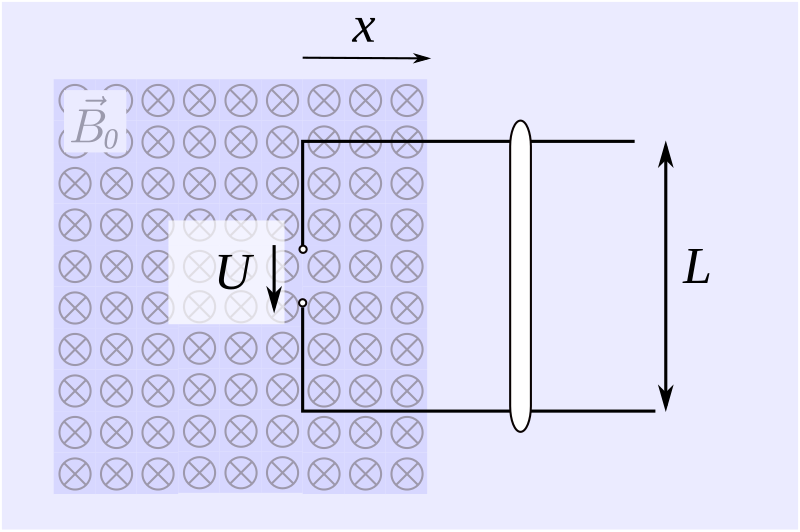
The diagram compares regions with different magnetic flux densities passing through the same area. It visually reinforces that altering the magnetic field strength changes the flux Φ, and therefore the flux linkage NΦ. The image introduces no additional ideas beyond the dependence of flux on field strength and area. Source.
Changing coil orientation
Rotating a coil relative to the field changes the angle involved in flux calculation, altering Φ steadily or sinusoidally.Changing area of the coil exposed to the field
Varying the effective area—for example, through motion—modifies Φ.Moving the coil into or out of a magnetic field
Motion-induced changes occur when a conductor physically moves through regions with different magnetic flux densities.
In each case, the induced e.m.f. depends on how swiftly these changes occur. A slow variation produces a small e.m.f., whereas a rapid change gives a much larger one.
A single complete sentence must appear between definition or equation blocks as required, ensuring clarity of explanation and avoiding dense clustering of formal content.
Modelling Changing Magnetic Flux Situations
To apply Faraday’s law in varied situations, it is useful to recognise the typical contexts in which flux linkage changes. Although deriving complex expressions is unnecessary at this level, students benefit from conceptualising how different systems produce time-dependent flux.
Rotating Coils
In many generators and electromagnetic devices, the rotation of a coil within a uniform magnetic field creates a continuously changing flux linkage.
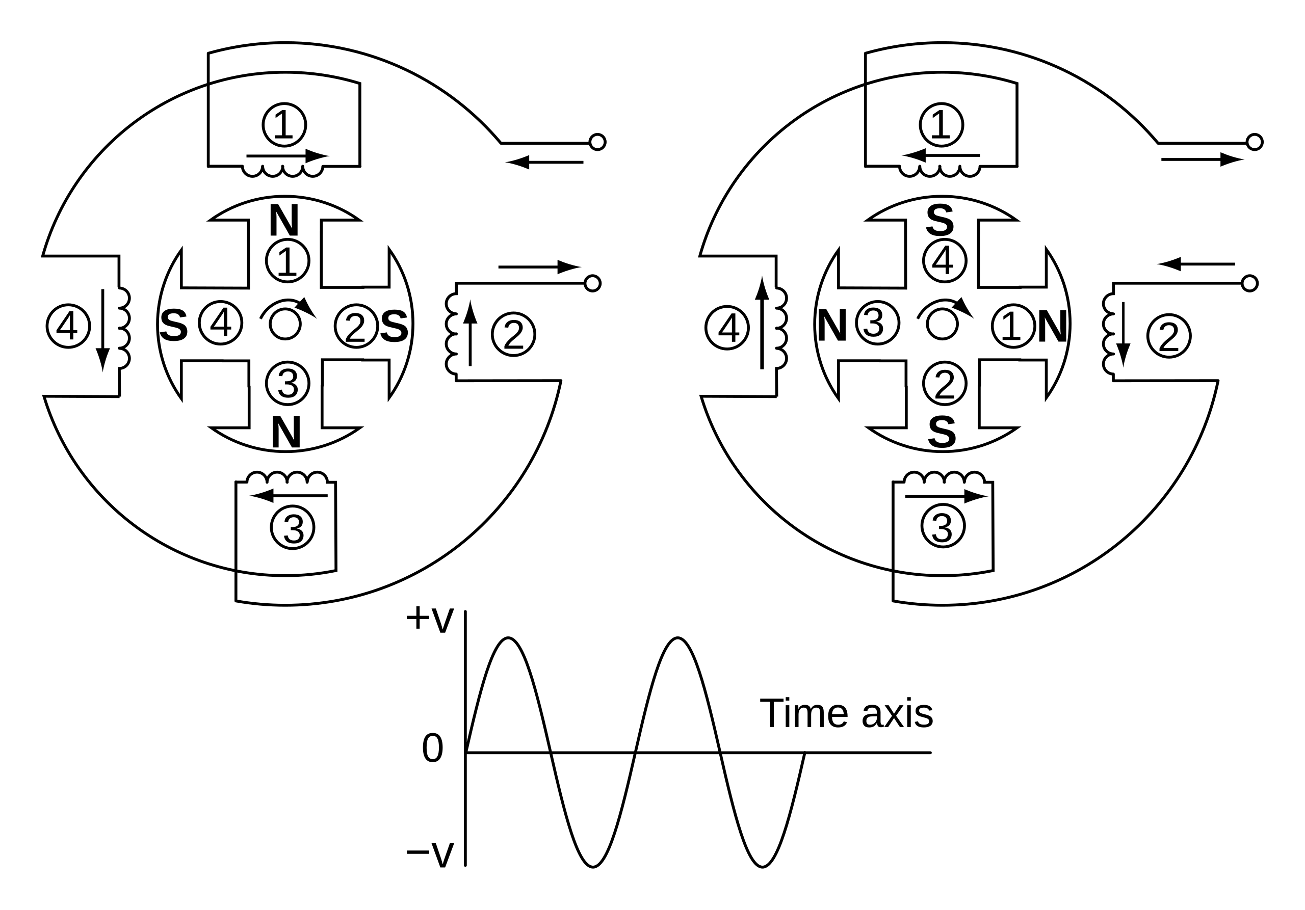
As the rotor coil turns between four magnetic poles, the magnetic flux linkage NΦ through the coil changes with time, inducing an alternating e.m.f. This provides a concrete example of E = −d(NΦ)/dt in action. The diagram includes extra engineering detail about pole arrangement and coil connections that exceeds syllabus requirements but aids visualising a realistic changing-flux situation. Source.
As the angle between the coil’s plane and the magnetic field alters, Φ changes in a predictable, usually sinusoidal, pattern. This produces an alternating e.m.f. whose frequency matches the rotational motion.
Translational Motion of Conductors
When a straight conductor moves perpendicularly through a magnetic field, the effective area swept out changes, altering flux. For a coil, the same idea applies when it is inserted or withdrawn from a magnetic region. The faster the motion, the greater the rate of change of flux linkage and thus the induced e.m.f.
Strength-Changing Magnetic Fields
Electromagnets, solenoids, or experimental setups may involve magnetic fields that vary with time. As B changes, so does Φ for any stationary coil within the field. This scenario is essential in situations such as switching circuits or alternating current systems where magnetic fields oscillate.
Practical Interpretation for A-Level Physics
To work confidently with induced e.m.f., it is crucial to recognise which aspect of the system is changing: field strength, orientation, area, or position. Students should be comfortable identifying the cause of flux variation and relating this to the magnitude and direction of the induced e.m.f.
Key points include:
Faster flux changes produce larger induced e.m.f.s.
Increasing coil turns amplifies induced voltage for the same flux change.
Opposition to change is an inherent feature captured by the negative sign in the induction equation.
Faraday’s law underlies the operation of many electromagnetic devices used in power generation and measurement.
Practice Questions
Question 1 (2 marks)
A coil is placed in a region of magnetic flux that decreases uniformly with time. Explain why an e.m.f. is induced in the coil and state the factor that determines the magnitude of this induced e.m.f.
Question 1 (2 marks)
• Changing magnetic flux through the coil induces an e.m.f. (Faraday’s law). (1)
• Magnitude depends on the rate of change of flux linkage (d(NPhi)/dt). (1)
Question 2 (5 marks)
A rectangular coil with 200 turns rotates at a constant angular speed in a uniform magnetic field.
(a) Explain why the magnetic flux linkage through the coil varies with time as it rotates.
(b) Describe how this variation in flux linkage leads to an alternating e.m.f. across the coil.
(c) State two changes that could be made to increase the maximum induced e.m.f., and explain why each change is effective.
Question 2 (5 marks)
(a)
• As the coil rotates, the angle between its plane (or normal) and the magnetic field changes. (1)
• This causes the magnetic flux through the coil to vary with time. (1)
(b)
• A changing flux linkage induces an e.m.f. (Faraday’s law). (1)
• The flux linkage changes in a sinusoidal or repeating manner due to rotation, producing an alternating e.m.f. (1)
(c)
Any two of the following, with explanation:
• Increase the number of turns N — increases flux linkage, so a greater change per unit time gives a larger e.m.f. (1)
• Increase magnetic field strength — increases flux, giving a larger rate of change. (1)
• Increase the coil area — increases flux through each turn, giving a larger change as it rotates. (1)
FAQ
The induced e.m.f. depends on flux linkage, which is the product of magnetic flux and the number of turns. Even if each turn experiences the same flux, adding more turns multiplies the total change in flux linkage.
This means every turn contributes its own induced effect, and these individual contributions add together to produce a larger overall e.m.f.
The negative sign represents Lenz’s law, showing that the induced e.m.f. opposes the change that causes it. For direction-based questions, the sign is crucial.
For magnitude-only questions, such as calculating the size of an induced voltage, the negative sign is usually omitted, as only the size of the induced e.m.f. is required.
A changing magnetic field always produces an induced e.m.f., but it only produces a current if the conductor is part of a complete circuit.
Open circuits still experience an induced potential difference, but no current flows. Closed circuits allow induced currents, which in turn can generate their own magnetic fields that oppose the original change.
The frequency of the induced e.m.f. matches the rate at which the flux linkage completes full cycles. Doubling the rotational speed doubles the number of cycles per second.
This means the flux linkage varies more rapidly, increasing both the frequency and the rate of change of flux, which in turn increases the induced e.m.f. amplitude.
If the area remains constant, coil shape has little effect on the basic induced e.m.f. because flux depends only on the perpendicular area exposed.
However, shape can influence practical factors:
Closely packed shapes reduce resistance and improve efficiency.
Certain shapes allow better alignment with the magnetic field.
Mechanical considerations may make some shapes easier to rotate smoothly.
These factors affect performance in devices but do not alter the fundamental induction relationship.
