
OCR Specification focus:
‘Use F = kx and determine effective k for springs or wires in series and parallel arrangements.’
The force constant (k) quantifies how stiff a spring or wire is, describing how much force is needed to produce a given extension. Understanding this constant and how it behaves in series and parallel systems is crucial for analysing mechanical systems, designing materials, and interpreting elastic behaviour within the elastic limit of materials.
The Force Constant and Hooke’s Law
Hooke’s Law Overview
Hooke’s Law forms the foundation for studying the relationship between force and extension in elastic materials such as springs and wires. It applies as long as the material is within its elastic limit, where deformation is reversible.
EQUATION
—-----------------------------------------------------------------
Hooke’s Law (Force–Extension Relationship) = F = kx
F = Force applied to the spring or wire (newtons, N)
k = Force constant or spring constant (newtons per metre, N m⁻¹)
x = Extension or compression from the equilibrium position (metres, m)
—-----------------------------------------------------------------
This equation shows that the force needed to extend or compress a spring is directly proportional to its extension, with the proportionality constant being k, the force constant. The larger the value of k, the stiffer the material or spring.
Defining the Force Constant
Force Constant (k): A measure of a spring’s stiffness; it represents the force required to produce a unit extension.
For an ideal spring, k remains constant within the linear, proportional region of the force–extension graph. Beyond this region, the material may deviate from Hooke’s law, and permanent deformation can occur.
Determining the Force Constant Experimentally
The force constant can be determined by measuring how much a spring stretches when subjected to varying known forces.
Procedure overview:
Suspend a spring vertically and measure its natural length without load.
Add known weights incrementally, each adding a measurable force (F = mg).
Measure the corresponding extension (x) for each load.
Plot a force–extension graph; the gradient gives the force constant (k)
This practical approach ensures direct measurement and allows for verification of the proportional relationship between force and extension.
Springs in Combination Systems
Mechanical systems often contain multiple springs arranged in series or parallel. Understanding how these configurations affect the effective force constant (kₑₓₜ) allows accurate predictions of overall stiffness and extension behaviour.
Springs in Series
When springs are connected end-to-end, the same force acts through each spring, but the extensions add up.

Two springs connected in series supporting a single load. In series, each spring carries the same force and the total extension is the sum of individual extensions, so 1/keff=1/k1+1/k21/k_\text{eff}=1/k_1+1/k_21/keff=1/k1+1/k2. The image is a clean SVG line drawing with minimal labels, ideal for OCR A Level revision; no extraneous content. Source.
Each spring stretches independently according to its own stiffness.
EQUATION
—-----------------------------------------------------------------
Springs in Series (Effective Force Constant) =
1/kₑₓₜ = 1/k₁ + 1/k₂ (+ 1/k₃ ... for more springs)
—-----------------------------------------------------------------
In a series arrangement:
The total extension is the sum of individual extensions.
The system behaves as if it has a lower effective stiffness.
The effective force constant kₑₓₜ is smaller than that of any single spring.
Thus, springs in series are softer than the individual springs alone. This principle is applied in mechanical systems designed for shock absorption, where greater flexibility or compliance is needed.
Springs in Parallel
When springs are connected side by side, they share the load, and each spring experiences the same extension, though the total force is divided between them.

Two springs connected in parallel supporting a single load. In parallel, the extension is the same for each spring and forces add, so keff=k1+k2k_\text{eff}=k_1+k_2keff=k1+k2 and the system is stiffer than either spring alone. The diagram is a simple SVG with clear geometry and no clutter. Source.
EQUATION
—-----------------------------------------------------------------
Springs in Parallel (Effective Force Constant) =
kₑₓₜ = k₁ + k₂ (+ k₃ ... for more springs)
—-----------------------------------------------------------------
In a parallel arrangement:
The extension is the same for all springs.
The total restoring force is the sum of forces** from each spring.
The system behaves as if it has a greater effective stiffness.
Therefore, springs in parallel are stiffer than individual springs.
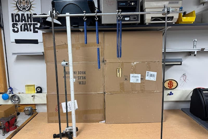
Laboratory rigs showing single, series, and parallel spring arrangements with masses. The photos illustrate the different extensions for the same or comparable loads, highlighting that keffk_\text{eff}keff decreases in series and increases in parallel. Extra detail: the image also shows stands, rods, and scales used for the demo, which are not required by the syllabus but aid interpretation. Source.
This configuration is ideal for systems requiring rigidity or load-bearing strength, such as suspension components in vehicles.
Comparing Series and Parallel Arrangements
The contrast between series and parallel configurations illustrates how system design affects mechanical behaviour:
Series systems → Greater overall extension for a given force → Lower effective stiffness.
Parallel systems → Smaller extension for a given force → Higher effective stiffness.
This understanding enables engineers and physicists to tune mechanical systems for specific performance criteria, balancing flexibility and rigidity as needed.
Force Constant in Wires
The same principles apply to wires under tension, which behave like springs when stretched elastically. For a uniform wire:
EQUATION
—-----------------------------------------------------------------
Force Constant for a Wire = (EA) / L
E = Young modulus (N m⁻²)
A = Cross-sectional area of the wire (m²)
L = Original length of the wire (m)
—-----------------------------------------------------------------
This relation links the microscopic material property (Young modulus) with the macroscopic behaviour (force constant). Increasing cross-sectional area or material stiffness increases k, while a longer wire decreases it.
This reinforces the concept that the force constant reflects not only material stiffness but also geometric factors, which must be considered in design and analysis.
Practical Applications of Force Constant Concepts
Understanding and calculating force constants for springs and wires enables accurate prediction of system responses in various contexts:
Measuring unknown forces in experimental setups using calibrated springs.
Designing mechanical supports and damping systems, such as shock absorbers.
Tuning resonance and oscillation frequencies in mass–spring systems, where frequency depends on k/m.
Evaluating material performance and selecting suitable stiffness for engineering components.
By combining theoretical principles and experimental methods, the force constant (k) becomes a central parameter in analysing both simple elastic systems and complex structures.
Practice Questions
Question 1 (2 marks)
A single spring has a force constant of 25 N m⁻¹. A second identical spring is connected in parallel with the first.
Calculate the effective force constant of the combined system.
Mark scheme:
Correct application of formula for parallel springs: k_total = k₁ + k₂ (1 mark)
Substitution and final answer: 25 + 25 = 50 N m⁻¹ (1 mark)
Question 2 (5 marks)
Two springs, X and Y, are connected in series and support a 2.0 N load.
Spring X has a force constant of 20 N m⁻¹ and spring Y has a force constant of 30 N m⁻¹.
(a) Calculate the effective force constant for the system. (3 marks)
(b) Determine the total extension of the combined springs under the 2.0 N load. (2 marks)
Mark scheme:
(a)
Correct series formula: 1/k_total = 1/k₁ + 1/k₂ (1 mark)
Substitution: 1/k_total = 1/20 + 1/30 (1 mark)
Correct final answer: k_total = 12 N m⁻¹ (1 mark)
(b)
Correct application of Hooke’s law: F = kx → x = F/k_total (1 mark)
Substitution and answer: x = 2.0 / 12 = 0.17 m (1 mark)
FAQ
As temperature increases, the material’s atomic vibrations become greater, slightly reducing its stiffness. This leads to a decrease in the force constant (k) because the material becomes easier to stretch or compress.
At low temperatures, the reverse happens — the material stiffens and k increases. However, for metals within normal laboratory conditions, the effect is small enough to be neglected in most OCR A-Level calculations.
In a series configuration, each spring carries the same force, but each spring extends according to its own stiffness.
Each extension adds up, producing a larger total extension.
The load is effectively distributed across the springs, meaning the system behaves as if it is softer overall.
This makes series arrangements useful when a greater range of movement or flexibility is needed, such as in vibration damping systems.
Yes. When combining springs of different stiffnesses:
In series, the overall system is dominated by the weaker (softer) spring, giving a smaller effective k.
In parallel, the system is dominated by the stiffer spring, giving a larger effective k.
Engineers exploit this by mixing spring types to achieve a balance between flexibility and strength in mechanical systems.
At high applied forces, the atomic bonds within the material begin to stretch beyond their linear range. The proportionality between force and extension no longer holds because:
Some atomic bonds start to rearrange permanently, leading to plastic deformation.
Microstructural changes (like dislocations) occur, reducing the material’s ability to recover elastically.
Beyond this point, the graph of force versus extension curves, marking the limit of proportionality.
Common sources of error include:
Parallax error when reading extension from a ruler not aligned with the spring.
Zero error if the spring’s natural length is measured incorrectly.
Mass of the spring itself causing extra extension, especially for light loads.
Dynamic effects if the spring is still oscillating during measurement.
Reducing these errors improves the accuracy of force constant (k) measurements and ensures data better represents true elastic behaviour.
