HL only core ideas
Electromagnetic induction happens when magnetic flux changes through a conductor or coil.
Magnetic flux is the amount of magnetic field passing through an area: .
In , is the angle between the magnetic field and the normal to the area.
Flux increases when increases, area increases, or the field becomes more perpendicular to the surface.
No induced emf unless there is a change in flux.
A change in flux can come from changing field strength, area inside the field, or orientation of the conductor/coil.
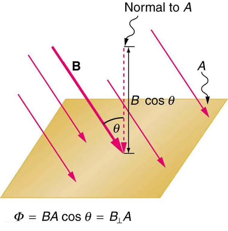
This diagram shows why only the component of the magnetic field perpendicular to the surface contributes to magnetic flux. It is the key picture for remembering why . Use it to explain why rotating a coil changes flux even if and stay constant. Source
Faraday’s law
A time-changing magnetic flux induces an emf.
Faraday’s law: .
is the number of turns in the coil, so more turns give a larger induced emf.
The induced emf is larger when the flux change is bigger or happens in a shorter time.
Exam idea: focus on what is changing in the flux expression — , , or .
Typical induction situations include time-varying magnetic fields, magnet/coil relative motion, and rotating coils.
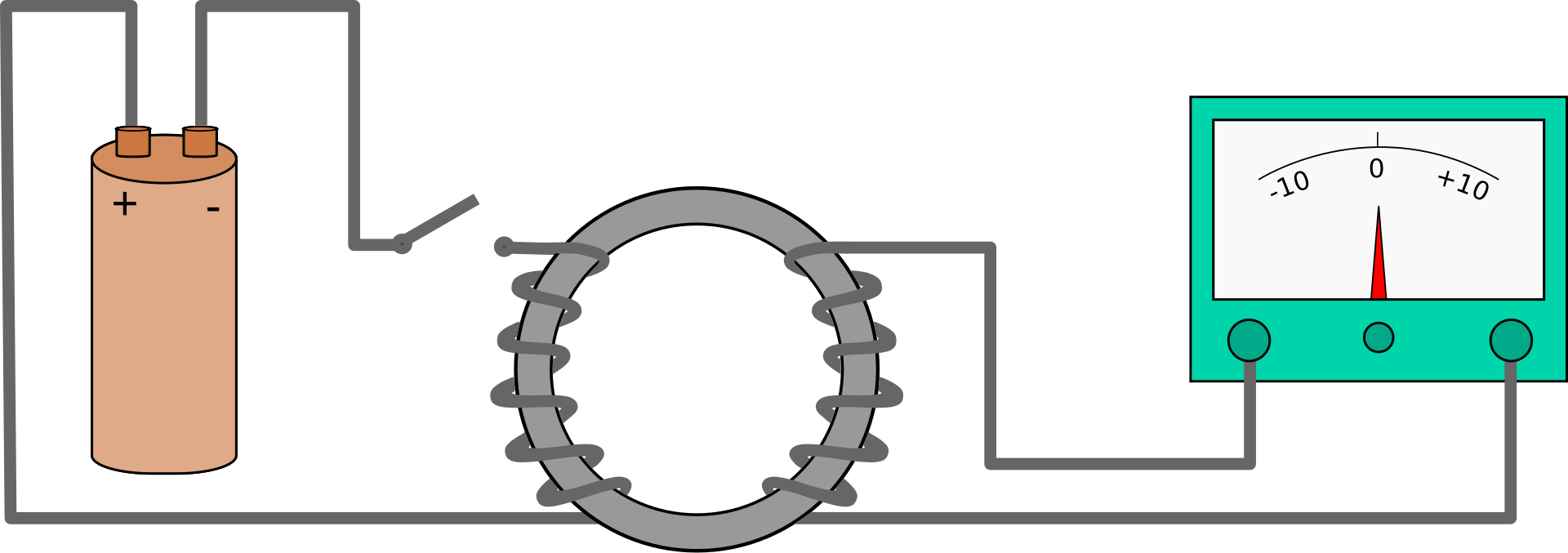
This image shows the classic induction experiment: a current in one coil changes the magnetic flux through a second coil, producing an induced emf. It is useful for linking changing flux directly to induced current. It also reinforces that a steady flux does not keep inducing emf. Source
Lenz’s law and direction of induced emf
The direction of induced emf/current is given by Lenz’s law.
The induced current always acts so that its magnetic effect opposes the change in flux that caused it.
The minus sign in Faraday’s law represents this opposition.
Lenz’s law is a consequence of conservation of energy.
If the induced current helped the change instead of opposing it, energy would be created from nowhere.
In exam questions, first decide whether the magnetic flux is increasing or decreasing, then choose the induced field that opposes that change.
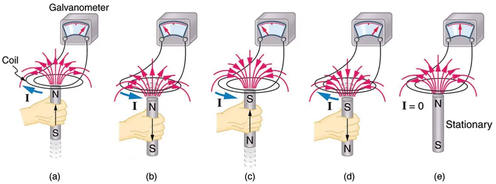
This image is ideal for explaining Lenz’s law because it shows that reversing the motion reverses the induced emf. It also shows that relative motion matters, not which object is moving. Use it to justify current direction in exam diagrams. Source
Motional emf in a straight conductor
A straight conductor moving perpendicularly through a uniform magnetic field has an induced emf.
Motional emf: .
This applies when the conductor moves at right angles to the field.
The induced emf increases with larger , larger speed , and greater conductor length in the field.
This is a special case of Faraday’s law because the motion changes the flux through the circuit.
Quantitative questions are restricted to straight conductors moving at right angles and rectangular coils moving in/out of fields.
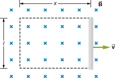
This figure shows how a moving rod changes the enclosed area, so the magnetic flux changes and an emf is induced. It connects the shortcut to the more general Faraday’s law. It is especially useful for explaining why faster motion gives a larger emf. Source
Rotating coils and generators
A coil rotating in a uniform magnetic field has a continuously changing angle , so its flux changes continuously.
This produces a sinusoidally varying emf.
A rotating coil is the basis of an electrical generator.
The induced emf is zero when the flux is momentarily at a maximum or minimum and greatest when the flux is changing most rapidly.
Increasing the frequency of rotation increases the rate of flux change, so the induced emf increases.
For exam explanations: mechanical energy is converted into electrical energy by changing magnetic flux.
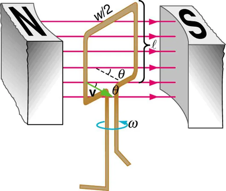
This image links a rotating coil directly to an alternating sinusoidal emf. It is the clearest visual for why increasing rotational frequency increases generator output. Use it whenever a question asks how generators work or how to raise induced emf. Source
Required practical and exam interpretation
Be able to explain induced emf in terms of change in magnetic flux, not just “movement”.
In diagrams, identify whether flux changes because of , , or .
For rectangular coils moving into or out of a field, focus on the part of the coil inside the field region.
Self-induction needs only a qualitative treatment.
Inductance and RL circuits are not required.
Checklist: can you do this?
Calculate magnetic flux using .
Use Faraday’s law to find induced emf and explain how changing , , or affects it.
Determine direction of induced current/emf using Lenz’s law.
Solve motional emf problems with .
Explain why a rotating coil produces a sinusoidal emf and why higher rotation frequency increases output.