
IB Syllabus focus:
'Calculating the force on a current-carrying conductor in a magnetic field using: F = B I L sinθ
Understanding the factors affecting the magnitude and direction of this force
Applications in motors, loudspeakers, and measurement instruments
Exploring the conditions for maximum force'
Calculating the Force
Formula and Variables
Diving into the core of this subtopic, we encounter a pivotal equation:
F = BILsinθ
where:
F is the force in newtons (N),
B is the magnetic flux density in teslas (T),
I is the current in amperes (A),
L is the length of the conductor within the magnetic field in meters (m), and
θ is the angle between the current’s direction and the magnetic field.
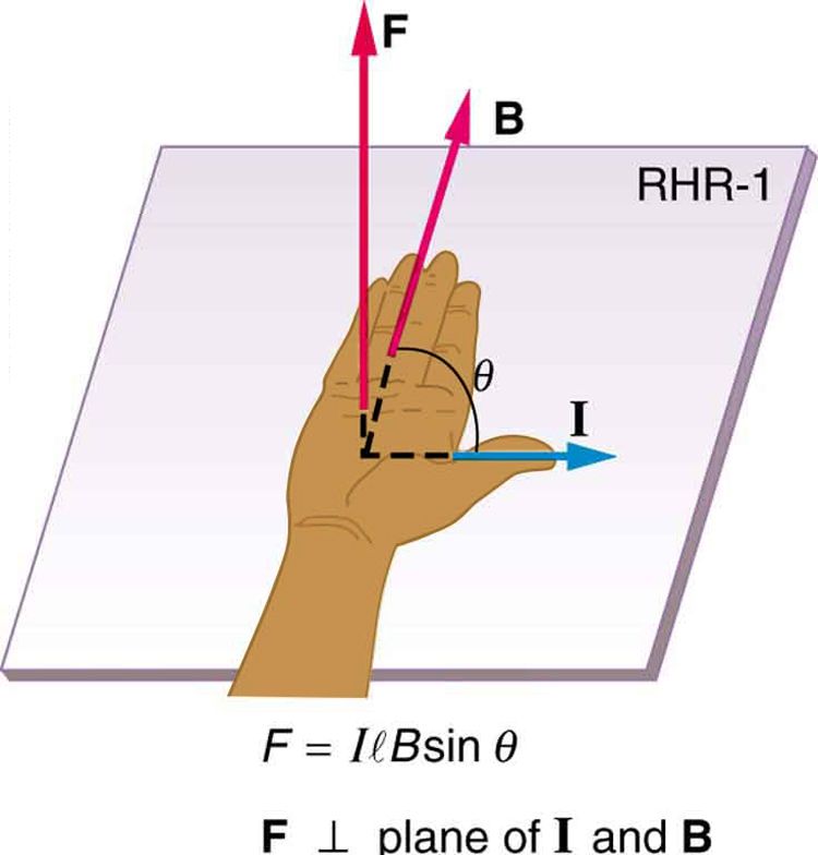
Force on a current-carrying conductor in magnetic field
Image Courtesy OpenStax
Dissecting the Equation
Practice Questions
FAQ
The shape and orientation of the conductor play a crucial role. A straight conductor experiences a uniform force along its length, but if the conductor is looped or coiled, the force distribution changes, leading to torque that causes rotational motion, like in electric motors. The orientation also matters; if more of the conductor's length is aligned perpendicularly to the magnetic field, the force is maximised, as indicated by the sinθ term in the equation F = BILsinθ. Hence, engineers often design conductors' shape and orientation to achieve desired force and motion characteristics in electromagnetic applications.
The direction of the force can be determined using Fleming’s left-hand rule. This rule states that if you extend your left hand with the thumb, forefinger, and middle finger perpendicular to each other (forming an ‘F’ shape), and the forefinger points in the direction of the magnetic field, the middle finger points in the direction of the current, then the thumb will point in the direction of the force experienced by the conductor. This rule is instrumental for understanding and predicting the movement and behaviour of current-carrying conductors in magnetic fields, underpinning the operation of many electromagnetic devices.
Indeed, the force on a current-carrying conductor in a magnetic field is employed in technologies like Maglev (Magnetic Levitation) trains. In these systems, the force balances the gravitational force, achieving levitation. A key principle here is electromagnetic induction. When the train moves, it induces a current in coils along the track, leading to a magnetic field that interacts with magnets on the train. The consequent magnetic force lifts and propels the train forward with minimal friction. This technology underscores the vast applications of the force on current-carrying conductors in magnetic fields beyond traditional domains, heralding innovations in transportation and other fields.
Yes, safety concerns are prevalent, especially in high-current scenarios. The force exerted on a current-carrying conductor in a magnetic field can lead to significant mechanical stress, leading to deformation or damage if not adequately managed. Moreover, a large current can result in overheating, posing a fire hazard or damaging the insulation, leading to short circuits. Engineers and scientists must consider these factors when designing and operating systems that involve substantial currents and magnetic fields, implementing adequate safety protocols, insulation, cooling systems, and materials to withstand the mechanical stress.
The material of the conductor affects its electrical resistance, and in turn, the current that flows through it when a voltage is applied. Different materials have different resistivities, impacting the current's intensity and therefore the force experienced in a magnetic field. For example, conductors made of materials with lower resistivity, like copper or aluminium, allow a larger current to flow, leading to a stronger force when placed in a magnetic field according to the equation F = BILsinθ. Choosing an appropriate conductor material is vital in applications like motors to ensure efficiency and performance.
