
OCR Specification focus:
‘Use W = ½QV, W = Q²/(2C), and W = ½CV² to calculate the energy stored by a capacitor.’
Capacitor energy equations provide a quantitative way to determine how much energy an isolated or circuit-connected capacitor can store when charged. These relationships arise from fundamental definitions of charge, potential difference, and capacitance, and allow prediction of how physical changes in a capacitor influence its stored electrical energy.
The Energy Stored in an Electric Field
The key idea underpinning capacitor energy storage is that separating charge across two plates creates an electric field. Work must be done to move charge onto the plates, and this work becomes stored energy. As more charge accumulates, the potential difference increases proportionally, so the work done is not constant per unit charge. Instead, it forms a rising relationship that leads to the three interchangeable energy equations used in A-Level Physics.
Before using these equations, it is important to understand the underlying quantities, particularly charge, potential difference, and capacitance, because their definitions determine how the equations relate to one another.
Charge (Q): The quantity of electric charge stored on a capacitor’s plates, measured in coulombs (C).
The concept of charge accumulation allows us to relate the plate separation, electric field strength, and potential difference across a capacitor.
A capacitor’s ability to store charge at a given potential difference is expressed through its capacitance.
Capacitance (C): The ratio of charge stored to potential difference across a capacitor, defined as C = Q/V, measured in farads (F).
This means a capacitor with a higher capacitance can store more charge for the same potential difference. As charging continues, increasing energy is needed to move additional charge against the higher p.d., which leads to the characteristic energy expressions.
Deriving the Capacitor Energy Equations
The three OCR-required equations describe the same physical energy using different variables. They originate from the p.d.–charge relationship and represent the area under a graph of V against Q. Because this graph is a straight line through the origin, the area—and thus the energy stored—is a triangle.
Graphically, the energy stored by a capacitor is equal to the area under a graph of potential difference V against charge Q.
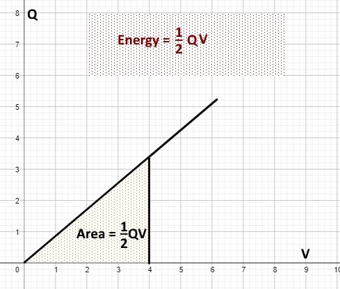
A Q–V graph showing the triangular region representing the work done to charge a capacitor. The shaded area corresponds to the energy stored, leading directly to the equation W = ½QV. This illustrates how the geometric area under the graph defines the capacitor’s stored energy. Source.
The first equation encountered by most students focuses directly on the charge and final potential difference of the capacitor.
EQUATION
—-----------------------------------------------------------------
Energy Stored in a Capacitor (W) = ½ Q V
W = Energy stored (joules, J)
Q = Charge stored (coulombs, C)
V = Potential difference across capacitor (volts, V)
—-----------------------------------------------------------------
This relationship demonstrates that energy storage depends jointly on how much charge a capacitor holds and the potential difference it has reached. Since both Q and V rise during charging, the factor of ½ reflects the increasing work required as the plates approach their final separation of charge.
Although W = ½QV is the most intuitive graph-based form, many practical situations require equations expressed in terms of capacitance and either charge alone or voltage alone. These rearrangements come from substituting Q = CV into the above equation.
After examining the version using Q and V, it is helpful to express energy purely in terms of charge when potential difference is less convenient to measure.
EQUATION
—-----------------------------------------------------------------
Energy Stored Using Charge Only (W) = Q² / (2C)
W = Energy stored (J)
Q = Charge stored (C)
C = Capacitance (F)
—-----------------------------------------------------------------
This equation highlights that a capacitor with larger capacitance stores less energy for a given charge, because a larger capacitor requires less work to hold that charge at a lower potential difference.
A single sentence must separate this from the next equation block to meet the formatting requirement, so note that the final standard form places emphasis instead on the potential difference across the capacitor plates.
EQUATION
—-----------------------------------------------------------------
Energy Stored Using Voltage Only (W) = ½ C V²
W = Energy stored (J)
C = Capacitance (F)
V = Potential difference (V)
—-----------------------------------------------------------------
This form is extremely useful when analysing circuits where the supply voltage is known but the charge is not directly measurable. It immediately shows that stored energy increases with the square of the voltage, illustrating how a modest rise in potential difference can significantly increase stored energy.
Choosing the Most Useful Equation
Because all three expressions describe the same physical quantity, the most appropriate equation depends on what information is available. Students should consider the following:
When Q and V are both known
Use W = ½QV, as this relates most clearly to the work done in establishing the electric field.
When Q is known but V is not
Use W = Q²/(2C), which eliminates the need to calculate potential difference.
When V is known but Q is not
Use W = ½CV², especially useful in circuit design or when working with known supply voltages.
Key Points for Examination
The energy stored is the work done to transfer charge to the capacitor plates.
The factor ½ appears because charge and potential difference increase proportionally during charging.
All three equations must be memorised and recognised as equivalent.
Understanding variable relationships allows prediction of how changes in capacitance, charge, or voltage affect stored energy.
In all three forms of the energy equation, the same quantity is being described: electrostatic potential energy stored in the electric field between the capacitor plates.
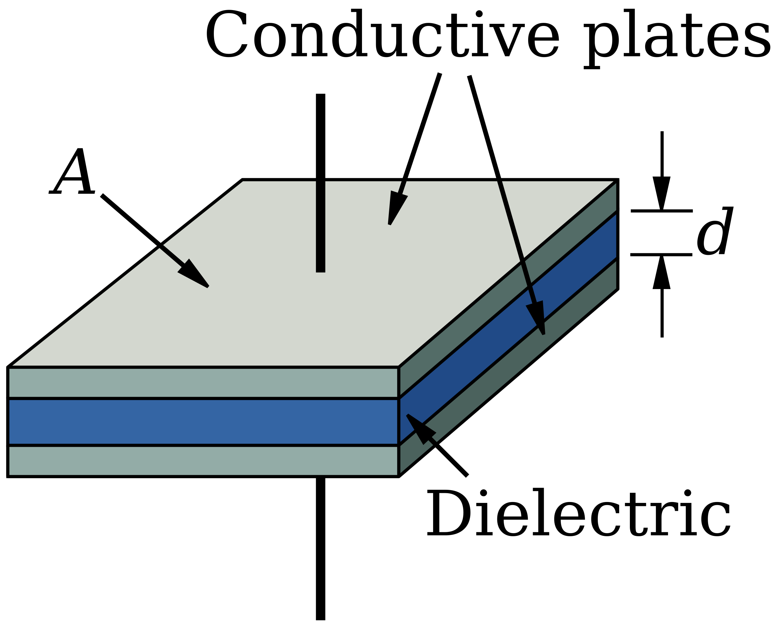
Diagram of a parallel-plate capacitor showing the plates, separation, and dielectric region. The energy given by the three equations is stored in the electric field between these plates. Labels such as A and d add structure detail beyond the syllabus but help link the equations to the physical capacitor. Source.
Practice Questions
Question 2 (5 marks)
A capacitor of capacitance 2200 microfarads is connected across a variable power supply.
(a) Explain why the energy stored in the capacitor increases with the square of the potential difference.
(b) The power supply is set to 18 V. Calculate the energy stored in the capacitor.
(c) State one practical reason why capacitors used in circuits often have a maximum voltage rating printed on them.
Question 2 (5 marks)
(a)
• Recognition that V increases while charging, so work done per unit charge increases (1 mark)
• Statement that energy is proportional to the area under a Q–V graph, which forms a triangle (1 mark)
• Linking triangular area to W = 1/2 CV2, showing dependence on V squared (1 mark)
(b)
• Correct use of equation: W = 1/2 CV2 (1 mark)
• Correct numerical answer: W = 0.36 J (accept 0.35–0.36 J depending on rounding) (1 mark)
(c)
• Any valid reason, e.g. to prevent dielectric breakdown, avoid damage or overheating, ensure safe operation (1 mark)
Question 1 (2 marks)
A capacitor stores a charge of 0.040 C at a potential difference of 12 V.
Calculate the energy stored in the capacitor.
Question 1 (2 marks)
• Correct use of energy equation: W = 1/2 QV (1 mark)
• Substitution and correct final answer: W = 0.24 J (accept answers in range 0.23–0.24 J due to rounding) (1 mark)
FAQ
The factor 1/2 appears because the potential difference across a capacitor does not remain constant while it charges. It increases from 0 to its final value.
Since each additional unit of charge is moved against a rising potential difference, the work done is the average of the initial and final values. This average is half the final potential difference, giving rise to the 1/2 factor in all forms of the energy equation.
All three equations come from combining W = 1/2 QV with the definition of capacitance, C = Q/V.
By substituting Q = CV or V = Q/C into W = 1/2 QV, you obtain the two alternative forms. This means:
• Use Q = CV to derive W = 1/2 CV2
• Use V = Q/C to derive W = Q2 / (2C)
Each equation expresses the same physical quantity but in a form suited to different known variables.
Indirectly, yes. The energy equations themselves do not refer to geometry, but the capacitance value does.
Design features that change capacitance include:
• Plate area
• Plate separation
• Dielectric material
These factors determine how much charge the capacitor can store at a given potential difference, and therefore how much energy it can ultimately hold.
For a fixed charge Q, a larger capacitance results in a lower potential difference because V = Q/C.
Since energy can be written as W = 1/2 QV, lowering V reduces the stored energy. The charge is spread more effectively across a capacitor with greater capacitance, so less work is needed to store that same charge.
This relationship highlights why selecting the correct capacitance value is important in energy storage applications.
As energy increases, the electric field between the plates strengthens. This does not involve moving mechanical parts but does involve changes within the dielectric.
The dielectric experiences:
• Greater polarisation
• Increased alignment of molecular dipoles
• Higher electric stress within the material
If the field becomes too strong, dielectric breakdown can occur, which is why voltage limits are specified for all practical capacitors.
