
OCR Specification focus:
‘Electromotive force (e.m.f.) is energy supplied per unit charge by a source.’
Electromotive force (e.m.f.) represents the energy conversion process within electrical sources, describing how energy is supplied to electric charges to enable current flow throughout a circuit. It underpins the understanding of how cells, batteries, and generators sustain electrical energy transfer.
The Concept of Electromotive Force
In physics, the electromotive force is a measure of how much energy per coulomb a source provides to move electric charge through a circuit. Although the term suggests a “force”, e.m.f. is not a mechanical force, but a form of potential difference specific to energy supply.
Electromotive Force (e.m.f.): The energy supplied by a source to each coulomb of charge that passes through it.
The e.m.f. represents the driving potential within a source that enables charge carriers (usually electrons) to move through external and internal circuit components. It acts as the origin of energy transfer, contrasting with potential difference (p.d.), which relates to energy transfer between points in the circuit as charges do work on components.
Sources of Electromotive Force
Chemical Cells and Batteries
In a chemical cell, a redox reaction generates an e.m.f. by converting chemical energy into electrical energy. The reactions at the electrodes establish a potential difference, maintaining continuous charge movement when connected to a closed circuit.
Generators and Alternators
In a generator, e.m.f. is induced through electromagnetic induction, where a changing magnetic field causes charges in a conductor to move. This mechanical-to-electrical energy conversion is a key principle in large-scale power production.
Photovoltaic Cells
In solar cells, e.m.f. arises from the photoelectric effect, where photons liberate charge carriers in a semiconductor material, establishing an internal potential difference without chemical or mechanical processes.
Quantifying Electromotive Force
EQUATION
—-----------------------------------------------------------------
Energy–Charge Relationship (E.m.f.)
E = W / Q
E = Electromotive force (volts, V)
W = Energy supplied by the source (joules, J)
Q = Charge moved (coulombs, C)
—-----------------------------------------------------------------
This equation shows that the e.m.f. of a source equals the energy supplied per unit charge. A larger e.m.f. means more energy is delivered to each coulomb, enabling higher energy transfer rates for given circuit conditions.
Between e.m.f. and terminal potential difference (t.p.d.), some energy is always lost internally — typically as heat within the source’s internal resistance.
Internal Resistance and Terminal Potential Difference
All real sources possess internal resistance (r), arising from the materials inside the cell or generator that impede current. As current increases, more energy is dissipated internally, reducing the energy available to the external circuit.
EQUATION
—-----------------------------------------------------------------
Source Voltage Relationship
E = V + Ir
E = Electromotive force (volts, V)
V = Terminal potential difference (volts, V)
I = Current in the circuit (amperes, A)
r = Internal resistance (ohms, Ω)
—-----------------------------------------------------------------
This relationship illustrates that the terminal voltage (V) across a source’s terminals is always slightly less than its e.m.f., except when no current flows.
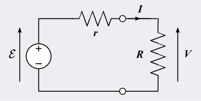
A non-ideal voltage source model: a source of e.m.f. E in series with internal resistance r, supplying a load R. The diagram clarifies why the terminal p.d. V is less than E when current flows, consistent with E = V + I r. Labels are minimal and directly map to the variables defined in the notes. Source.
When the circuit is open (I = 0), terminal p.d. equals e.m.f. because there is no internal voltage drop.
In a closed circuit, as current increases, the term Ir grows, meaning terminal voltage falls due to internal energy losses.
Distinguishing E.m.f. from Potential Difference
Although both quantities are measured in volts, their physical meanings differ:
E.m.f. refers to the energy supplied by a source per coulomb of charge.
Potential difference (p.d.) refers to the energy transferred or used per coulomb of charge as current flows through a component.
Thus, e.m.f. is associated with energy input, while p.d. represents energy output within the circuit.
When a charge travels around a complete loop in a circuit, the total e.m.f. supplied equals the total p.d. across all components, maintaining the principle of energy conservation.
Measurement of Electromotive Force
Using a Voltmeter
To measure e.m.f., a high-resistance voltmeter is connected across the terminals of a source when no current flows. Under open-circuit conditions, the voltmeter reading gives the true e.m.f., as there is no internal voltage loss.
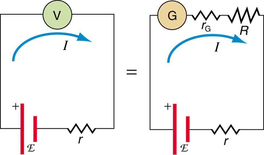
A standard voltmeter draws a small current, so it typically measures terminal p.d. V, not the e.m.f. The diagram highlights the role of internal resistance r and motivates open-circuit or null methods for accuracy. Extra detail: the figure includes an equivalent analog-meter circuit, which goes slightly beyond the syllabus but helps explain why the reading differs from E. Source.
Using a Potentiometer
For greater precision, a potentiometer can determine e.m.f. by balancing it against a known potential difference, ensuring no current flows through the source during measurement.
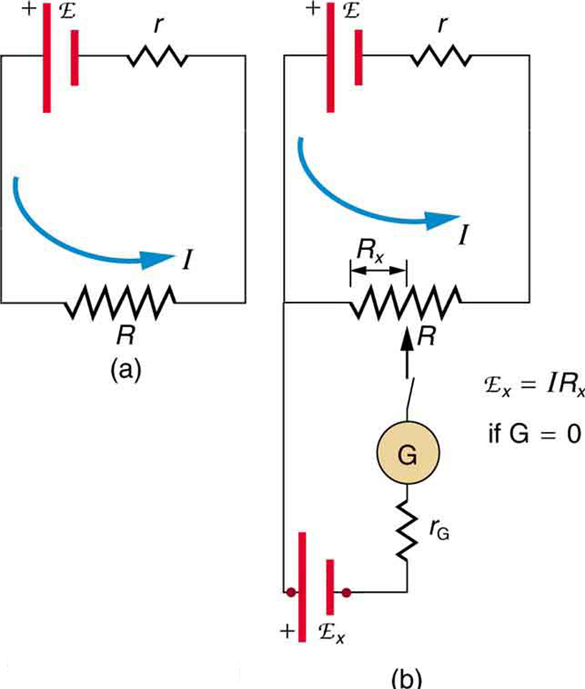
Potentiometer (null method): a constant current flows through a long uniform resistor, and a movable contact selects a point where the galvanometer reads zero when opposed by the unknown cell. At balance, no current leaves the cell being measured, so the reading corresponds to its true e.m.f. The figure uses simple labels and shows only the elements required for OCR coverage. Source.
This method avoids errors caused by internal resistance, giving an accurate measurement of the energy supplied per charge.
Energy Transfer within the Source
Within any electrical source, the e.m.f. represents a conversion from non-electrical to electrical energy:
Chemical → Electrical (in cells and batteries)
Mechanical → Electrical (in generators)
Light → Electrical (in photovoltaic cells)
This process involves moving charge carriers through an internal energy field or reaction mechanism, increasing their electrical potential energy before they enter the external circuit.
The total energy supplied to each coulomb equals the sum of energy used externally and the energy dissipated internally. Efficient energy sources aim to minimise internal resistance to ensure that most of the e.m.f. is available for external work.
Practical Context and Relevance
Understanding e.m.f. is essential for:
Analysing circuit energy distribution.
Designing efficient power sources with low internal losses.
Interpreting performance characteristics of cells and batteries.
Relating theoretical equations to real-world energy conversion processes.
In electrical systems, recognising that e.m.f. defines the source’s capability to supply energy allows students to predict and calculate voltage behaviour, power output, and energy efficiency across diverse circuit applications.
Practice Questions
Question 1 (2 marks)
Define electromotive force (e.m.f.) and explain how it differs from potential difference (p.d.) in an electrical circuit.
Mark scheme:
1 mark: States that e.m.f. is the energy supplied per unit charge by a source.
1 mark: Explains that p.d. is the energy transferred or used per unit charge between two points in a circuit, whereas e.m.f. is the energy supplied by the source.
Question 2 (5 marks)
A cell has an e.m.f. of 6.0 V and an internal resistance of 0.50 Ω. It is connected to an external resistor of 11.5 Ω.
(a) Calculate the current in the circuit. (2 marks)
(b) Determine the terminal potential difference across the cell. (2 marks)
(c) Explain why the terminal potential difference is less than the e.m.f. of the cell. (1 mark)
Mark scheme:
(a)
1 mark: Correctly uses E = V + Ir or rearranges to I = E / (R + r).
1 mark: Substitutes correctly and calculates I = 6.0 / (11.5 + 0.50) = 0.49 A (2 s.f.).
(b)
1 mark: Uses V = E – Ir.
1 mark: Substitutes correctly and calculates V = 6.0 – (0.49 × 0.50) = 5.8 V (2 s.f.).
(c)
1 mark: Explains that energy is lost as heat inside the cell due to its internal resistance, so the terminal potential difference is lower than the e.m.f..
FAQ
The e.m.f. of a cell can decrease as chemical reactants are used up, reducing the rate of energy conversion within the cell.
Temperature also affects reaction rates — lower temperatures slow the chemical processes, slightly reducing e.m.f.
In rechargeable cells, repeated charge–discharge cycles can degrade electrodes, increasing internal resistance and causing a gradual drop in e.m.f. over time.
E.m.f. measures the energy supplied to each coulomb of charge, regardless of how quickly the charge moves.
Current, however, depends on how many charges move per second. Since e.m.f. relates to the energy conversion process, not the rate of charge flow, it is defined per unit charge to describe the potential energy gained by a single coulomb within the source.
Yes — the e.m.f. of a source is constant for a given state of the source, but terminal voltage changes with current.
When current increases:
More energy is lost across the internal resistance (Ir).
Terminal voltage drops, even though the e.m.f. remains the same.
When no current flows (open circuit), the terminal voltage equals the e.m.f.
Generators rely on electromagnetic induction, where a conductor moving through a magnetic field experiences a changing magnetic flux.
According to Faraday’s law, this change induces an e.m.f. proportional to the rate of flux change.
Mechanical energy (rotation) is therefore converted into electrical energy as charges are driven around the circuit. The e.m.f. direction follows Lenz’s law, opposing the change that caused it.
Common errors include:
Current flowing during measurement, causing a lower terminal voltage reading.
Contact resistance at connections, which introduces small voltage drops.
Temperature changes in wires or cells, altering internal resistance.
To minimise these:
Use a potentiometer for a null method, ensuring no current flows through the source.
Allow the cell to stabilise thermally before taking readings.
