
OCR Specification focus:
‘Distinguish e.m.f. and p.d. by where energy is supplied or transferred in a circuit.’
Electrical circuits involve energy transfer from sources to components. Understanding the difference between electromotive force (e.m.f.) and potential difference (p.d.) is crucial for analysing how electrical energy is supplied and used within a circuit.
Understanding Energy Transfer in Circuits
In any electrical circuit, energy moves as charged particles (usually electrons) flow. The source, such as a cell or power supply, provides energy, while circuit components like resistors or lamps convert that energy into other forms, such as heat or light. The concepts of e.m.f. and p.d. describe these energy exchanges quantitatively and conceptually.
Electromotive Force (e.m.f.)
Electromotive force refers to the total energy supplied by a source to each unit of charge that passes through it. Despite its name, e.m.f. is not a force, but rather an energy per charge quantity.
Electromotive Force (e.m.f.): The energy supplied per unit charge by a source, such as a cell or generator, to drive charge around a complete circuit.
When charge carriers pass through the internal chemistry or mechanism of the source, energy is transferred from chemical or mechanical forms into electrical energy. This process raises the potential energy of the charges.
EQUATION
—-----------------------------------------------------------------
Electromotive Force (E) = W ÷ Q
E = electromotive force, measured in volts (V)
W = energy supplied, measured in joules (J)
Q = charge moved, measured in coulombs (C)
—-----------------------------------------------------------------
After receiving this energy, the charges can perform work in other parts of the circuit. The e.m.f. thus represents the input energy per coulomb of charge into the circuit from its power source.
Potential Difference (p.d.)
Potential difference describes the energy transferred or used by electrical charge as it moves between two points in a circuit, typically across a component like a resistor or lamp.
Potential Difference (p.d.): The energy transferred per unit charge between two points in a circuit due to electrical work done by the charge.
EQUATION
—-----------------------------------------------------------------
Potential Difference (V) = W ÷ Q
V = potential difference, measured in volts (V)
W = energy transferred, measured in joules (J)
Q = charge moved, measured in coulombs (C)
—-----------------------------------------------------------------
Whereas e.m.f. relates to energy gained by charge, p.d. corresponds to energy lost or transferred by charge as it passes through circuit elements. Components such as bulbs, heaters, or resistors convert this electrical energy into other forms.
Distinguishing e.m.f. and p.d. Conceptually
While the equations for e.m.f. and p.d. are identical in form, their meanings differ based on where the energy transfer occurs in a circuit.
Direction of Energy Transfer
Electromotive force represents energy supplied to the charge by a source.
Potential difference represents energy transferred from the charge to components.
Thus, e.m.f. is associated with the input of energy to the circuit, and p.d. with the output of energy from the circuit.
In a Complete Circuit
When current flows:
The battery or power supply provides energy to the charges (e.m.f.).
The components use that energy, converting it to other forms (p.d.s across components).
The sum of all potential differences around a closed loop equals the total e.m.f. supplied, in accordance with energy conservation.
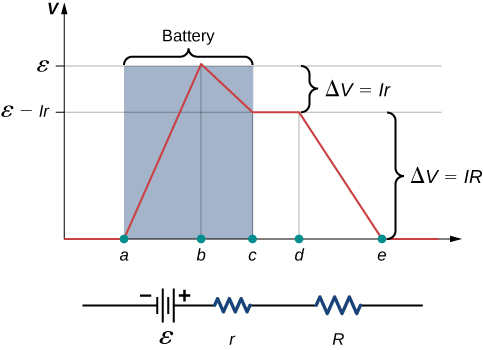
Voltage changes around a simple circuit with a real battery. The diagram marks the rise ε in the source, the drop Ir inside the battery (internal resistance), and the external drop IR across the load, so that ε = V + Ir. This directly illustrates how terminal p.d. is less than e.m.f. when current flows. Source.
This relationship means that if a 6 V cell drives a current through a circuit, and the sum of voltage drops across all resistors and devices is 6 V, the energy supplied by the cell equals the energy transferred by the components each second.
Measuring e.m.f. and p.d.
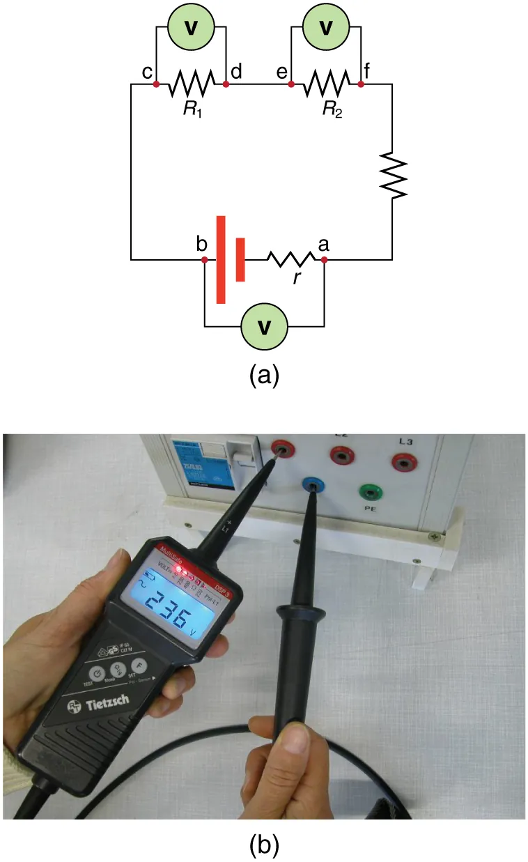
Voltmeter connections for measuring potential difference. In (a), voltmeters are placed in parallel with the source and with resistors, with terminal p.d. identified between points a and b. The diagram also labels the source’s internal resistance r, reinforcing that terminal p.d. can differ from the source e.m.f. when current flows. Source.
When no current flows, the terminal p.d. equals the e.m.f. of the source.
When current flows, the terminal p.d. is less than the e.m.f. because of internal resistance, which causes some energy to be lost inside the source itself.
Internal Resistance and Effective e.m.f.
Inside every real power supply, a small resistance known as internal resistance opposes charge flow. This means:
Part of the energy supplied by the source is dissipated internally.
The rest is available to the external circuit as terminal potential difference (V).
EQUATION
—-----------------------------------------------------------------
E = V + Ir
E = electromotive force (V)
V = terminal potential difference (V)
I = current in the circuit (A)
r = internal resistance of the source (Ω)
—-----------------------------------------------------------------
This equation shows that the energy per coulomb provided by the source (E) is divided between that used within the source (Ir) and that delivered to the external circuit (V).
Energy Perspective Summary
Energy transfer can be visualised through these roles:
e.m.f.: energy given to each coulomb by the source.
p.d.: energy lost by each coulomb as it moves through circuit elements.
The total energy supplied equals the total energy transferred, reinforcing the principle of conservation of energy.
Distinguishing Features
To clarify how these concepts differ in physical meaning:
Location in circuit
e.m.f. acts across the power source.
p.d. acts across components.
Type of energy change
e.m.f.: conversion of chemical or mechanical energy to electrical.
p.d.: conversion of electrical energy to other forms (heat, light, motion).
Measurement method
e.m.f.: measured when no current flows (open circuit).
p.d.: measured when current flows through the component.
Energy Flow in Real Circuits
In a real circuit:
The cell’s e.m.f. provides the driving energy.
The charges transport this energy through the wires.
The components experience potential differences, where energy is transferred to other forms.
Internal resistance slightly reduces the available energy for the external circuit, ensuring no system is perfectly efficient.
Practice Questions
Question 1 (2 marks)
Explain the difference between electromotive force (e.m.f.) and potential difference (p.d.) in terms of energy transfer within an electrical circuit.
Mark Scheme:
1 mark for stating that e.m.f. is the energy supplied per unit charge by a source to drive charge around a circuit.
1 mark for stating that p.d. is the energy transferred per unit charge by the charge to a component in the circuit (i.e. energy used or lost).
Question 2 (5 marks)
A battery of e.m.f. 12.0 V and internal resistance 0.50 Ω is connected to a lamp of resistance 5.5 Ω.
(a) Calculate the current in the circuit. (2 marks)
(b) Determine the terminal potential difference of the battery when the lamp is operating. (2 marks)
(c) Explain why the terminal potential difference is less than the e.m.f. of the battery. (1 mark)
Mark Scheme:
(a)
Correct application of formula: E = V + Ir or E = I(R + r) (1 mark)
Substitution and correct current: I = 12.0 / (5.5 + 0.5) = 2.0 A (1 mark)
(b)
Use of V = E – Ir (1 mark)
Correct substitution: V = 12.0 – (2.0 × 0.50) = 11.0 V (1 mark)
(c)
Statement that some energy is lost inside the battery due to internal resistance (1 mark)
(Accept equivalent explanations such as: “a potential difference exists across the internal resistance, reducing the terminal p.d.”)
FAQ
The term “electromotive force” dates back to early electrical research, when voltage was believed to push charges like a mechanical force.
Today, e.m.f. is understood as energy per unit charge, not a physical force. It represents how much energy a source gives each coulomb of charge, measured in volts. The historical name remains, but in physics contexts, students should think of it as an energy quantity, not a literal force.
Yes, some devices can act as both an energy source and an energy sink, depending on circuit conditions.
For example:
A rechargeable battery supplies energy (e.m.f.) during discharge.
The same battery has a potential difference acting against current when being charged, absorbing electrical energy instead.
Thus, whether something provides e.m.f. or exhibits p.d. depends on the direction of energy transfer relative to the charge flow.
Internal resistance results from the materials and processes inside the battery:
Electrolyte resistance as ions move between electrodes.
Contact resistance at the electrodes themselves.
Chemical reaction limitations, particularly at high current.
Together, these effects cause a small voltage drop inside the cell. As current increases, this drop grows (Ir), meaning less energy is available to the external circuit.
As the current drawn from a source increases, the terminal potential difference (V) decreases.
This happens because the internal resistance (r) causes a voltage drop Ir within the source.
When I increases, Ir increases proportionally.
Since E = V + Ir, a higher internal voltage drop means V falls even though E remains constant.
This effect is why high-current devices often cause batteries to “sag” or appear weaker under heavy load.
Yes. The principle of energy conservation ensures that:
The total energy supplied by the source (e.m.f.) equals
The total energy transferred across all potential differences in the circuit.
However, some of that energy may be lost as heat in internal resistance or in connecting wires.
Even though the useful energy output may drop, the total energy balance still holds true — it’s simply shared between useful transfer and internal dissipation.
