
OCR Specification focus:
‘State and apply conditions for equilibrium under forces and torques; use triangle of forces for three coplanar forces.’
In physics, equilibrium describes a state where all forces and torques acting on a body balance perfectly, ensuring no change in motion or rotation. Understanding equilibrium enables accurate analysis of structures, mechanisms, and natural systems.
The Nature of Equilibrium
A body is in equilibrium when both its translational and rotational motions remain constant — meaning there is no acceleration and no angular acceleration. This occurs when all external forces and torques are balanced. For equilibrium analysis, two essential conditions must always be met: one concerning forces, and the other concerning torques.
Translational Equilibrium
Translational equilibrium refers to the situation where the net (resultant) force on a body is zero. This ensures that the body does not accelerate linearly and either remains at rest or continues moving at a constant velocity.
Translational Equilibrium: A state in which the vector sum of all external forces acting on a body equals zero, resulting in no linear acceleration.
EQUATION
—-----------------------------------------------------------------
Condition for Translational Equilibrium: ΣF = 0
ΣF = Vector sum of all forces acting on the body (N)
—-----------------------------------------------------------------
This equilibrium condition applies separately in both horizontal and vertical directions, which is particularly useful for resolving forces acting at angles or on inclined surfaces.
Rotational Equilibrium
Rotational equilibrium is achieved when the sum of all moments (torques) about any point is zero. This ensures that the body does not rotate or, if already rotating, continues at a constant angular velocity.
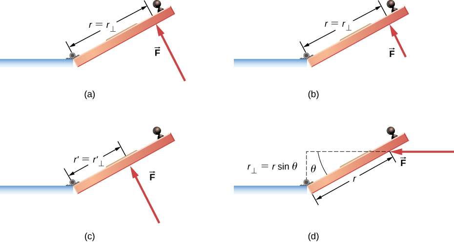
Torque is the rotational effectiveness of a force about a pivot. The figure shows how the same force produces different torques depending on perpendicular distance and angle, distinguishing clockwise and counterclockwise rotation. This supports the condition Στ = 0. Source.
Rotational Equilibrium: A state in which the sum of clockwise moments about any point equals the sum of anticlockwise moments, preventing angular acceleration.
EQUATION
—-----------------------------------------------------------------
Condition for Rotational Equilibrium: Στ = 0
τ = Torque or moment of a force (N m)
—-----------------------------------------------------------------
For a rigid body to be in complete equilibrium, both translational and rotational equilibrium must be satisfied simultaneously.
Forces in Equilibrium
When multiple forces act on a body, equilibrium requires that their vector sum equals zero. In diagrams, this can be visualised as the forces forming a closed polygon, typically a triangle for three coplanar forces.
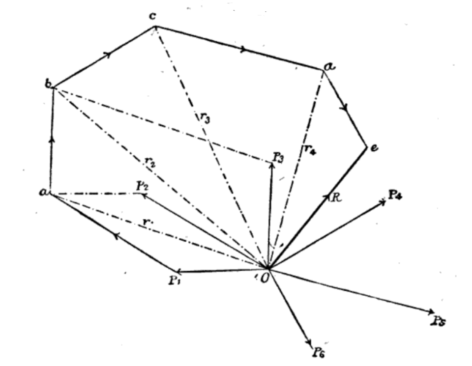
A polygon of forces represents forces tip-to-tail; closure of the polygon indicates zero resultant, i.e. translational equilibrium. For three forces, this becomes the triangle of forces used at A-Level. The historical figure shows a general polygon, but the principle is identical. Source.
Triangle of Forces
The triangle of forces is a graphical method for representing equilibrium involving three coplanar forces acting at a point.
Triangle of Forces: A condition where three coplanar forces acting on a body in equilibrium can be represented in magnitude and direction by the sides of a triangle taken in order.
This concept arises directly from vector addition: if three forces are in equilibrium, then F₁ + F₂ + F₃ = 0. When drawn tip-to-tail, the vectors form a closed triangle.
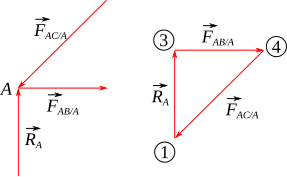
A triangle of forces diagram shows three coplanar forces in equilibrium represented by a closed triangle drawn to scale. This illustrates the OCR requirement to use the triangle of forces for three coplanar forces. Light structural node labels are present but do not affect interpretation. Source.
To apply this condition:
Draw each force as a vector in the correct direction and magnitude.
Connect them tip-to-tail.
If they form a closed triangle, the body is in equilibrium.
This graphical approach simplifies analysis, particularly in static systems such as beams, supports, and suspended objects.
Coplanar Forces
Coplanar forces are forces that act within the same plane. Most equilibrium problems at A-Level assume coplanar conditions. When more than three coplanar forces act on a body, vector resolution or algebraic methods are used to confirm that the resultant force is zero.
For equilibrium under coplanar forces:
Resolve all forces into horizontal and vertical components.
Ensure that the sum of components in each direction is zero.
Verify that moments about any chosen point also sum to zero.
EQUATION
—-----------------------------------------------------------------
Conditions for Coplanar Equilibrium:
ΣFₓ = 0
ΣFᵧ = 0
Στ = 0
Fₓ = Sum of horizontal components of forces (N)
Fᵧ = Sum of vertical components of forces (N)
τ = Sum of moments about a chosen point (N m)
—-----------------------------------------------------------------
These three conditions are sufficient to confirm equilibrium for planar systems.
Forces and Torques Acting Together
For equilibrium, forces and torques are interdependent. A system may have balanced forces but still rotate if torques do not balance. Conversely, balanced torques alone do not guarantee translational stability. Therefore:
All linear forces must balance to prevent translation.
All moments must balance to prevent rotation.
Examples include balanced beams, suspended signs, or static ladders — all depend on simultaneous fulfilment of both equilibrium conditions.
Checking Equilibrium in Practice
In practical and theoretical problems, the following structured process ensures correct analysis:
Identify all external forces acting on the object (including weight, normal reaction, tension, and friction).
Represent these forces with a free-body diagram.
Resolve angled forces into perpendicular components.
Choose a convenient pivot point for taking moments — often where unknown forces act.
Apply equilibrium conditions systematically:
ΣFₓ = 0 (horizontal balance)
ΣFᵧ = 0 (vertical balance)
Στ = 0 (rotational balance)
If all conditions hold true, the object is confirmed to be in equilibrium.
Applications of the Equilibrium Conditions
The principles of equilibrium underpin many physical and engineering systems:
Bridges and beams rely on balanced forces and torques to prevent collapse.
Cranes and levers use moment calculations to ensure safe load limits.
Suspended objects such as signs or lamps are designed with the triangle of forces to predict tension in cables.
Human biomechanics applies equilibrium to analyse posture and joint forces.
These examples demonstrate how theoretical equilibrium conditions translate directly into real-world stability and design efficiency.
Key Summary of Conditions for Equilibrium
A body is in equilibrium when:
The resultant of all forces acting on it is zero (ΣF = 0).
The resultant of all torques about any point is zero (Στ = 0).
For three coplanar forces, the triangle of forces can represent the equilibrium condition geometrically.
Together, these principles form the foundation for analysing both static and dynamic systems in mechanics, ensuring predictive control over motion and stability.
Practice Questions
Question 1 (2 marks)
A uniform metre rule is supported horizontally by two pivots placed 20 cm from each end. A 4.0 N weight is hung from the rule at the 30 cm mark.
State the two conditions that must be satisfied for the rule to remain in equilibrium.
Mark Scheme for Question 1 (2 marks)
(1 mark) The resultant (net) force on the rule must be zero (no translational acceleration).
(1 mark) The sum of clockwise moments must equal the sum of anticlockwise moments (no rotational acceleration).
Question 2 (5 marks)
A uniform beam of weight 80 N and length 2.0 m is supported horizontally by a wall hinge at one end (point A) and a cable attached to the other end (point B). The cable is fixed to a point on the wall vertically above A, making an angle of 30° to the horizontal.
(a) Draw a labelled free-body diagram of the beam. (2 marks)
(b) By taking moments about point A, calculate the tension in the cable. (3 marks)
Mark Scheme for Question 2 (5 marks)
(a) Free-body diagram (2 marks):
(1 mark) Correctly shows the weight (80 N) acting vertically down at the beam’s centre (1.0 m from A).
(1 mark) Shows the tension (T) in the cable acting upward at 30° to the horizontal from point B, and the reaction force at A (horizontal and vertical components or a single resultant).
(b) Taking moments about A (3 marks):
(1 mark) Correct use of moment equation:
Sum of clockwise moments = Sum of anticlockwise moments.
(80 × 1.0) = (T × 2.0 × sin 30°)(1 mark) Substitution and rearrangement:
T = (80 × 1.0) / (2.0 × 0.5)(1 mark) Correct final answer:
T = 80 N.
FAQ
In static equilibrium, a body remains completely at rest — both its linear and angular velocities are zero. This occurs when all forces and torques are balanced, and there is no motion.
In dynamic equilibrium, the body moves at constant velocity or angular velocity, meaning the forces and torques are still balanced but motion continues uniformly.
The key distinction is that static equilibrium involves no motion, while dynamic equilibrium allows motion without acceleration.
If a body is truly in equilibrium, the sum of moments about any point will equal zero. This means that choosing different pivot points simply provides different, but consistent, equations.
However, strategically choosing a pivot can simplify calculations — for instance:
Selecting the point where an unknown force acts eliminates that term from the moment equation.
This flexibility arises because equilibrium requires a complete balance of torques throughout the system.
Friction often provides the resisting torque or horizontal force necessary to maintain equilibrium.
For example:
A ladder resting against a wall depends on friction at the base to prevent slipping.
If friction is insufficient, the system will no longer satisfy ΣF = 0, and motion begins.
Thus, while ideal problems may neglect friction, in practice it plays a crucial role in maintaining both translational and rotational stability.
Yes. A system can have balanced torques yet experience a net unbalanced force.
For instance, if two equal parallel forces act in opposite directions but at different lines of action, their torques can cancel, resulting in no rotation.
However, the vector sum of the forces is not zero, so the object still accelerates linearly.
This demonstrates that rotational equilibrium alone does not ensure total equilibrium — both conditions must be satisfied.
When all forces act through the same point, they produce no moment about that point because the perpendicular distance (lever arm) is zero.
In this situation:
Only translational effects occur; there can be no rotation caused by these forces.
Equilibrium analysis reduces solely to ensuring ΣF = 0.
This condition is often seen in systems like a suspended mass on a string, where all forces (tension and weight) act through the same line of action.
