
OCR Specification focus:
‘Recognise and use symbols for sources, resistors, meters, switches, diodes, and sensors.’
Understanding common circuit components is essential for analysing and constructing electrical circuits accurately. Each symbol represents a distinct function, ensuring clarity and consistency in circuit diagrams and experimental setups.
Sources of Electrical Energy
Cells and Batteries
A cell provides electrical energy through chemical reactions that drive a flow of charge. When multiple cells are connected in series, they form a battery, increasing the total electromotive force (e.m.f.) available.
Electromotive force (e.m.f.): The energy supplied per unit charge by a source.
In circuit diagrams, a cell is shown as one long and one short line, representing the positive and negative terminals respectively. A battery is depicted as a series of alternating long and short lines. The longer line indicates the positive terminal, vital when determining current direction in conventional flow diagrams.
Power Supplies
Laboratory power packs and DC sources are drawn similarly to batteries, often with adjustable outputs. AC supplies are shown as a circle with a sine wave inside, signifying alternating current that reverses direction periodically. Understanding these distinctions helps in interpreting how energy is delivered in practical circuits.
Resistors and Their Variants
Fixed Resistors
A resistor opposes current flow, controlling potential difference distribution across a circuit. The standard symbol is a small rectangle.
Resistance: The opposition to current flow, measured in ohms (Ω).
Fixed resistors maintain a constant resistance value, used to limit current or divide voltage within a circuit.
Variable Resistors
A variable resistor (or rheostat) allows resistance adjustment, controlling the current in a circuit. It is symbolised by a rectangle with an arrow across it, indicating a changeable resistance value. This component is essential for calibrating circuit responses or dimming lights.
Potentiometers
A potentiometer divides potential difference. Its symbol is a resistor with three terminals and an arrow pointing to the middle. Rotating or sliding the wiper adjusts the voltage output between two points, useful in volume controls and voltage sensors.
Measuring Devices (Meters)
Ammeter
An ammeter measures electric current. It is connected in series with the circuit and represented by a circle containing the letter A.
Current (I): The rate of flow of electric charge, measured in amperes (A).
Ammeter resistance is very low to minimise circuit interference.
Voltmeter
A voltmeter measures potential difference between two points, connected in parallel. The symbol is a circle containing the letter V. Voltmeters have a very high resistance to prevent altering current flow through the circuit component being measured.
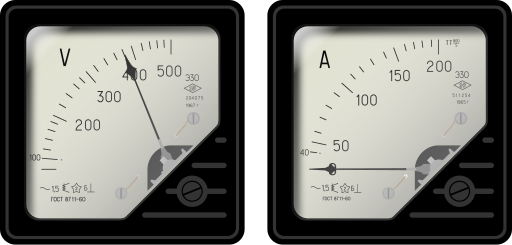
Clean IEC-style symbols for a voltmeter (V) and an ammeter (A). The voltmeter symbol reinforces parallel connection for potential difference, while the ammeter symbol shows series connection for current. Ideal for quick recognition. Source.
Galvanometer
A galvanometer detects small currents, particularly in bridge circuits. Its symbol resembles that of a meter with a G inside. It is highly sensitive and forms the basis of some analogue ammeters and voltmeters.
Switches and Circuit Control
Single-Pole Switches
A single-pole single-throw (SPST) switch controls one circuit branch, either open (off) or closed (on). It is represented by a break in the line with a movable contact. Switches are fundamental for circuit control and safety.
Double-Pole and Multi-Throw Switches
A double-pole switch controls two separate circuits simultaneously, shown as paired SPST symbols. A single-pole double-throw (SPDT) switch directs current between two outputs, common in selector circuits.
Push and Reed Switches
A push switch operates momentarily when pressed; its circuit closes only during contact. A reed switch closes magnetically and is often used in security systems or proximity sensors.
Diodes and Rectifying Devices
Standard Diode
A diode allows current to flow in one direction only. The symbol shows a triangle pointing towards a line—the triangle indicates the anode, and the line the cathode. Diodes are used for rectification, converting alternating current (AC) to direct current (DC).
Diode: A semiconductor device that permits current flow in one direction only.
Light-Emitting Diode (LED)
An LED emits light when forward biased. Its symbol is a diode with outward-pointing arrows, signifying emitted light. LEDs are energy-efficient and used in indicators, displays, and lighting.
Zener Diode
A Zener diode allows current flow in the reverse direction once a specific breakdown voltage is reached. It is essential for voltage regulation, with a symbol similar to a diode but featuring bent ends on the bar line.
Sensors and Dependent Devices
Light-Dependent Resistor (LDR)
An LDR has resistance that decreases as light intensity increases. The symbol is a resistor within a circle, with two arrows pointing towards it representing incoming light. LDRs are vital in automatic lighting and exposure sensors.

Standard LDR symbol with a resistor element inside a circle and incoming light arrows. This reinforces that resistance decreases as light intensity increases. Vector format ensures crisp scaling and clarity. Source.
Light-dependent resistor (LDR): A resistor whose resistance decreases as the light intensity incident on it increases.
LDRs are classified as photoresistors and are non-linear, with rapid resistance change under varying illumination.
Thermistor
A thermistor changes resistance with temperature. The negative temperature coefficient (NTC) type decreases resistance as temperature rises. The symbol resembles a resistor with a diagonal line and a small temperature marker.
Thermistor: A semiconductor resistor whose resistance varies significantly with temperature.
Thermistors are used in temperature sensing, control systems, and overcurrent protection.
Variable and Dependent Devices in Circuits
Variable components allow feedback and control in sensor circuits. For example:
LDRs in automatic lighting adjust current with brightness.
Thermistors in thermostats regulate heating systems.
Potentiometers act as adjustable voltage dividers for calibration.
Summary of Symbol Use in Circuit Design
To construct accurate and interpretable circuit diagrams:
Use standard OCR circuit symbols for clarity and consistency.
Label terminals and polarities on sources and diodes clearly.
Keep wire paths straight with right-angle junctions.
Include meters correctly connected—ammeters in series, voltmeters in parallel.
Identify variable components (e.g. potentiometers, thermistors) with arrows or annotations showing adjustability or dependency.
These conventions ensure that diagrams are universally understood and can be accurately translated into real circuit setups in laboratory and theoretical contexts.
Practice Questions
Question 1 (2 marks)
Identify and draw the correct circuit symbol for a light-dependent resistor (LDR). Explain how its resistance changes when the light intensity increases.
Mark Scheme
1 mark: Correctly draws the symbol — a resistor within a circle with two arrows pointing towards it.
1 mark: States that resistance decreases as light intensity increases.
Question 2 (5 marks)
A student is constructing a simple electrical circuit to investigate how different components behave.
(a) State the correct symbol for a voltmeter and describe where it should be placed in the circuit. (2 marks)
(b) The student includes a diode and a resistor in series. Explain how the current would behave if the battery connections were reversed, referring to the properties of the diode. (3 marks)
Mark Scheme
(a)
1 mark: Correctly identifies the voltmeter symbol — a circle with the letter V inside.
1 mark: States that the voltmeter must be connected in parallel with the component whose potential difference is being measured.
(b)
1 mark: Recognises that the diode allows current in one direction only (forward direction).
1 mark: Explains that when the battery is reversed, the diode becomes reverse-biased, preventing current flow.
1 mark: States that the resistor does not affect this directional property but would still limit current if conduction occurred.
FAQ
Standardised circuit symbols ensure that electrical diagrams are understood universally, regardless of country or manufacturer. This consistency allows engineers, students, and technicians to interpret and construct circuits accurately without confusion.
Standardisation also prevents errors during assembly, maintenance, and testing. The IEC (International Electrotechnical Commission) defines most modern circuit symbols used in A-level Physics, promoting uniformity across textbooks, examinations, and professional documentation.
Although both components control resistance, their applications differ:
A variable resistor (rheostat) adjusts current by altering resistance within a circuit branch — typically two terminals are used.
A potentiometer divides potential difference, usually employing all three terminals to provide an adjustable output voltage.
Variable resistors are used for current control (e.g. dimmers), whereas potentiometers serve as voltage adjusters (e.g. volume controls or calibration dials).
Semiconductors have electrical properties that change significantly with environmental factors such as light or temperature.
In an LDR, photons excite electrons, reducing resistance as light intensity increases.
In a thermistor, heating frees charge carriers, causing resistance to fall.
Metals cannot achieve these large, sensitive changes because their charge carriers are already abundant and relatively unaffected by such stimuli.
A diode must be connected the correct way round to conduct. The anode (positive side) should be connected to the higher potential and the cathode (negative side) to the lower potential.
If reversed, the diode becomes reverse-biased, blocking current flow except for a negligible leakage current. Exceeding the reverse breakdown voltage can permanently damage the diode or cause conduction through a different mechanism, as in Zener diodes.
Always check the power rating of resistors to prevent overheating.
Use appropriate current-limiting resistors with LEDs and diodes to avoid damage.
Disconnect the power supply before changing connections.
Ensure components are mounted securely to prevent short circuits.
In educational settings, low-voltage DC supplies are used to minimise electrical hazards while demonstrating these principles safely.
