
OCR Specification focus:
‘Interpret circuit diagrams to assemble practical circuits safely and accurately.’
Translating Between Circuit Diagrams and Practical Setups
Understanding how to translate between circuit diagrams and physical circuit setups is essential for building safe, accurate, and functional electrical circuits in both experimental and theoretical physics work.
Understanding Circuit Diagrams
Circuit diagrams are schematic representations of electrical circuits, showing components as standardised symbols rather than their physical shapes. This abstraction allows physicists to analyse and communicate circuit designs clearly and universally. Each symbol corresponds to a real component, such as a resistor, power supply, or switch, and the connections between them are represented by straight lines indicating conductive paths.
The Purpose of Circuit Diagrams
Circuit diagrams serve multiple functions:
To design and plan electrical systems efficiently before construction.
To communicate circuit layouts between scientists, engineers, and students using a consistent visual language.
To troubleshoot circuits by identifying potential errors or inefficiencies through logical analysis.
When moving from a diagram to a real setup, it is important to understand both what each symbol represents physically and how connections should be arranged in a practical context.
Interpreting Circuit Symbols in Real Circuits
Each circuit component has a recognised electrical symbol that corresponds to its real-world equivalent.
Circuit Symbol: A standardised graphical representation of an electrical component used in diagrams to convey its type and function.
To accurately translate a circuit diagram:
Identify each symbol and match it to its physical component (e.g., a cell, resistor, or lamp).
Ensure polarity is correctly followed for components such as batteries, diodes, and LEDs, where current must flow in one direction.
Note that junctions in circuit diagrams represent physical wire connections, whereas crossing lines without a junction do not indicate electrical contact.
Reading Circuit Connections
A circuit diagram does not usually show the physical layout or spatial positioning of components. Instead, it displays logical connections. Therefore, when building from a diagram:
Follow the connectivity, not the appearance. Wires in a diagram that are drawn straight or at right angles may be rearranged physically to fit the workspace.
Ensure that all components connected in series on the diagram are wired end-to-end.
Confirm that all parallel connections share common start and end points in the real setup.
Series and Parallel Arrangements
Series circuits: Components share the same current; the total voltage divides across them.
Parallel circuits: Components share the same voltage; the current divides between branches.
Understanding these arrangements ensures that the physical circuit behaves as predicted by the diagram.

A clear comparison of a two-resistor series circuit (left) and parallel circuit (right), using standard symbols. This visual emphasises that series elements share the same current while parallel branches share the same potential difference. The resistor values and 9 V label are included for context but are not required by the syllabus. Source.
Constructing Circuits Safely and Accurately
When translating a diagram to a real circuit:
Begin by checking the power supply type, voltage, and polarity.
Assemble the circuit step-by-step, verifying connections after each stage.
Use colour-coded wires if possible (e.g., red for positive, black for negative or ground) to prevent confusion.
Avoid overheating components, particularly when experimenting with variable resistors, thermistors, or bulbs.
Short Circuit: A connection where current bypasses the intended path, causing excessive current flow and potential damage or hazards.
To prevent such hazards, double-check that all paths correspond to the intended design and that no exposed conductors touch accidentally.
Mapping Practical Setups Back to Diagrams
Students often encounter practical circuits without diagrams, requiring reverse translation. The aim is to represent the physical circuit as a schematic:
Identify all components and note their electrical relationships.
Trace current flow paths to determine series and parallel groupings.
Draw symbols corresponding to each component in the correct logical positions.
Add labels for voltages, currents, and resistances where needed for clarity.
This reverse process helps solidify understanding of how circuit behaviour relates to its schematic form.
Tools and Measurement Integration
In both interpreting and constructing circuits, measuring instruments are crucial:
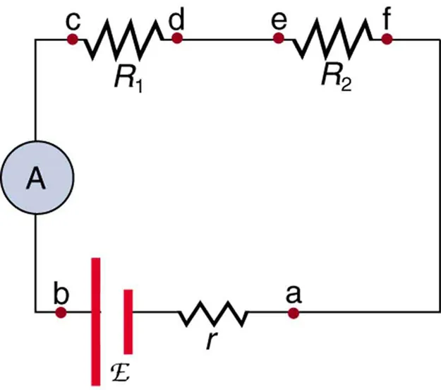
A standard schematic with an ammeter (A) placed in series so all branch current passes through the meter. This reinforces that series placement measures the intended current path and that moving the ammeter within the same series branch yields the same reading. The additional labels for internal resistance and emf extend beyond the syllabus but do not change the core message. Source.
Voltmeters are connected in parallel across the component to measure potential difference.
Potential Difference (p.d.): The energy transferred per unit charge between two points in a circuit, measured in volts (V).
EQUATION
—-----------------------------------------------------------------
Energy Transfer (W) = Potential Difference (V) × Charge (Q)
W = Energy transferred (joules, J)
V = Potential difference (volts, V)
Q = Charge (coulombs, C)
—-----------------------------------------------------------------
Although this equation underpins circuit operation, its practical application lies in verifying that measured voltages align with theoretical expectations from the diagram.
Recognising Circuit Equivalence
When translating between diagrams and setups, several physical arrangements can be electrically equivalent, meaning they perform identically despite differing in physical shape.
Rearranging components or wires physically does not change circuit function if the electrical connections remain identical
Identifying nodes (points where two or more components join) ensures accurate mapping between schematic and practical versions.
This skill becomes particularly useful when troubleshooting or modifying circuits for experiments.
Verification and Testing
After assembling a circuit:
Inspect visually for incorrect or loose connections.
Use a multimeter to test continuity and confirm component placement.
Switch on power only after verifying that resistors, lamps, and other elements are connected as intended.
If the circuit does not behave as expected, compare the actual setup carefully to the original diagram, checking that each junction and component is present and correctly oriented.
Summary of Good Practice When Translating
When moving between diagrams and practical setups:
Always use standard circuit symbols for clarity and consistency.
Maintain safe, neat wiring and avoid unnecessary tangles.
Label components when necessary to aid understanding.
Confirm that every symbol and connection corresponds accurately to its physical counterpart.
Develop confidence by practising both directions — from diagram to setup and from setup to diagram — reinforcing conceptual and practical understanding.
Translating between circuit diagrams and setups combines theoretical comprehension with practical precision, a core skill in experimental physics essential for safe, effective circuit work.
Practice Questions
Question 1 (2 marks)
A student is asked to construct a circuit from a diagram showing a cell, a resistor, and a lamp connected in series.
State two checks the student should make to ensure the practical circuit matches the circuit diagram.
Mark scheme:
Correctly connects the components in series as shown in the diagram (1 mark)
Ensures all positive and negative terminals are oriented correctly (1 mark)
(Allow 1 mark for any other valid check, e.g. that all junctions match the diagram and that there are no unintended connections or short circuits.)
Question 2 (5 marks)
A circuit diagram shows a cell connected to a resistor and an LED. An ammeter is connected to measure the current through the LED, and a voltmeter is connected across the LED.
(a) Describe how the student should assemble this circuit safely and accurately using the diagram.
(b) Explain why the ammeter and voltmeter must be connected in different ways.
Mark scheme:
(a) Assembling the circuit (up to 3 marks):
Identifies that the ammeter is connected in series with the LED to measure the current through it (1 mark)
States that the voltmeter is connected in parallel across the LED to measure potential difference (1 mark)
Notes correct polarity: the LED’s anode connected to the positive terminal of the cell (1 mark)
Mentions ensuring low voltage/power source is used and circuit is switched off while connecting (1 mark, max 3 total for part a)
(b) Explanation (up to 2 marks):
Ammeters have low resistance so they do not significantly affect the current (1 mark)
Voltmeters have high resistance so they draw negligible current, ensuring an accurate measurement of potential difference (1 mark)
FAQ
One frequent mistake is copying the diagram’s physical layout exactly rather than following the electrical connections. Wires in a real setup may need to be rearranged, but the logical connections must remain identical.
Students also sometimes:
Forget to include or correctly orient components such as diodes and LEDs.
Confuse series and parallel branches when multiple connections meet.
Fail to connect ammeters or voltmeters in the correct configuration.
Checking each connection against the circuit diagram systematically prevents these errors.
A reliable method is to use a continuity test with a multimeter before applying power. This ensures that all intended connections exist and no unwanted short circuits are present.
Alternatively, students can:
Trace each connection from the power source through every component in turn.
Tick off each wire and junction on a printed copy of the diagram as it is verified.
This approach reduces mistakes, especially in circuits with many branches or sensors.
Right-angle junctions and straight wires make circuit diagrams clear and unambiguous. They allow anyone reading the diagram to distinguish between connections and simple wire crossings.
Without this convention, a circuit could be misread — for example, a crossing of two lines without a junction could be mistaken for an electrical connection. Adhering to neat, angular wiring ensures accuracy when translating diagrams to practical setups.
Simplify the circuit to show functional sections rather than physical positions. Group related components, such as sensors or measuring devices, logically within the schematic.
Key points:
Each section should have its own clear loop or branch.
Common reference points (like ground or negative terminals) should be shown consistently.
Label all supply voltages and meter connections explicitly.
This abstraction helps both in understanding and in safely constructing complex circuits.
Circuit diagrams act as logical maps for fault-finding. By comparing expected connections and measurements with the real circuit, students can systematically locate errors.
Typical fault-finding process:
Begin from the power source and follow the circuit path.
Measure current and voltage at key points.
Compare results with theoretical predictions from the diagram.
Discrepancies often reveal loose connections, reversed components, or damaged devices, allowing targeted corrections.
