
OCR Specification focus:
‘Use standard circuit symbols as set out in recognised guidance for 16–19 science.’
Standard electrical circuit symbols form the essential visual language of physics and engineering, allowing students, teachers, and professionals to communicate circuit designs clearly and universally.
The Role of Standard Electrical Symbols
Electrical symbols are simplified graphic representations of components in an electrical or electronic circuit. Their purpose is to ensure that circuit diagrams can be understood across different countries, exam boards, and professional contexts.
By adhering to recognised international standards—such as those from the Institute of Physics (IOP) and British Standards (BS 3939)—students can interpret and draw circuits that are both accurate and consistent.
Circuit symbols eliminate ambiguity in diagrams. They serve as a universal shorthand, meaning that even complex circuits can be communicated without excessive text. Using these correctly is essential for exam accuracy, experimental reliability, and safe practical assembly.
Common Categories of Electrical Symbols
Circuit symbols fall into key categories according to their function in a circuit. Each symbol represents how the component behaves and how it connects electrically.
Sources and Power Supplies
Power sources provide energy to the circuit. These are the starting point for current flow.
Examples include:
Cell: Represented by a long and short line pair, showing positive and negative terminals.
Battery: Two or more cells connected in series.
Power supply (d.c. or a.c.): Indicated by circle symbols with plus/minus or sine wave markings.
Electromotive force (e.m.f.): The energy supplied per unit charge by a source such as a cell or battery.
It is crucial to show the polarity of the cell or supply clearly, since incorrect orientation changes current direction and can damage components.

Cell and battery symbols with terminal polarity marked by long (positive) and short (negative) plates. Recognising polarity ensures conventional current direction is interpreted correctly. The simple series circuit shown is an acceptable extra detail that aligns with symbol usage. Source.
Conductors and Connections
Wires and junctions show how components are connected. In diagrams, wires should be represented as straight lines that meet at right angles.
Conducting wire: A simple straight line representing a path for current.
Connected wires (junction): Shown by a dot at the crossing point.
Unconnected wires: Lines that cross but do not touch—often drawn with a small bridge to show no connection.
Clear wiring reduces confusion, especially in circuits with multiple branches. Avoid diagonal or curved lines, as these reduce legibility.
Control Components: Switches and Variable Devices
Switches control the current flow in circuits.
Common symbols include:
Open switch: Break in the circuit; current cannot flow.
Closed switch: Complete circuit; current flows freely.
Push switch: Only conducts when pressed.
Two-way switch: Directs current between alternative paths.
Variable components adjust circuit conditions such as resistance.
Variable resistor: A resistor with an arrow indicating adjustable resistance.
Potentiometer: Three-terminal device used to divide voltage.
Thermistor: A temperature-dependent resistor, symbolised by a diagonal line and small temperature marking.
Light-dependent resistor (LDR): A resistor symbol with two inward-pointing arrows representing incident light.
Variable resistor: A resistor whose resistance can be manually altered to control current or voltage.
Using the correct form of these symbols distinguishes between manual and sensor-based control in circuits.
Measurement Instruments
Accurate measurement requires correct instrument symbols:
Ammeter: Measures current; represented by a circle with an “A.”
Voltmeter: Measures potential difference; circle with a “V.”
Galvanometer: Sensitive current detector; circle with “G.”
These instruments are always shown in series (ammeters) or in parallel (voltmeters) relative to the component under test. Proper diagram representation helps predict and interpret measurement results accurately.
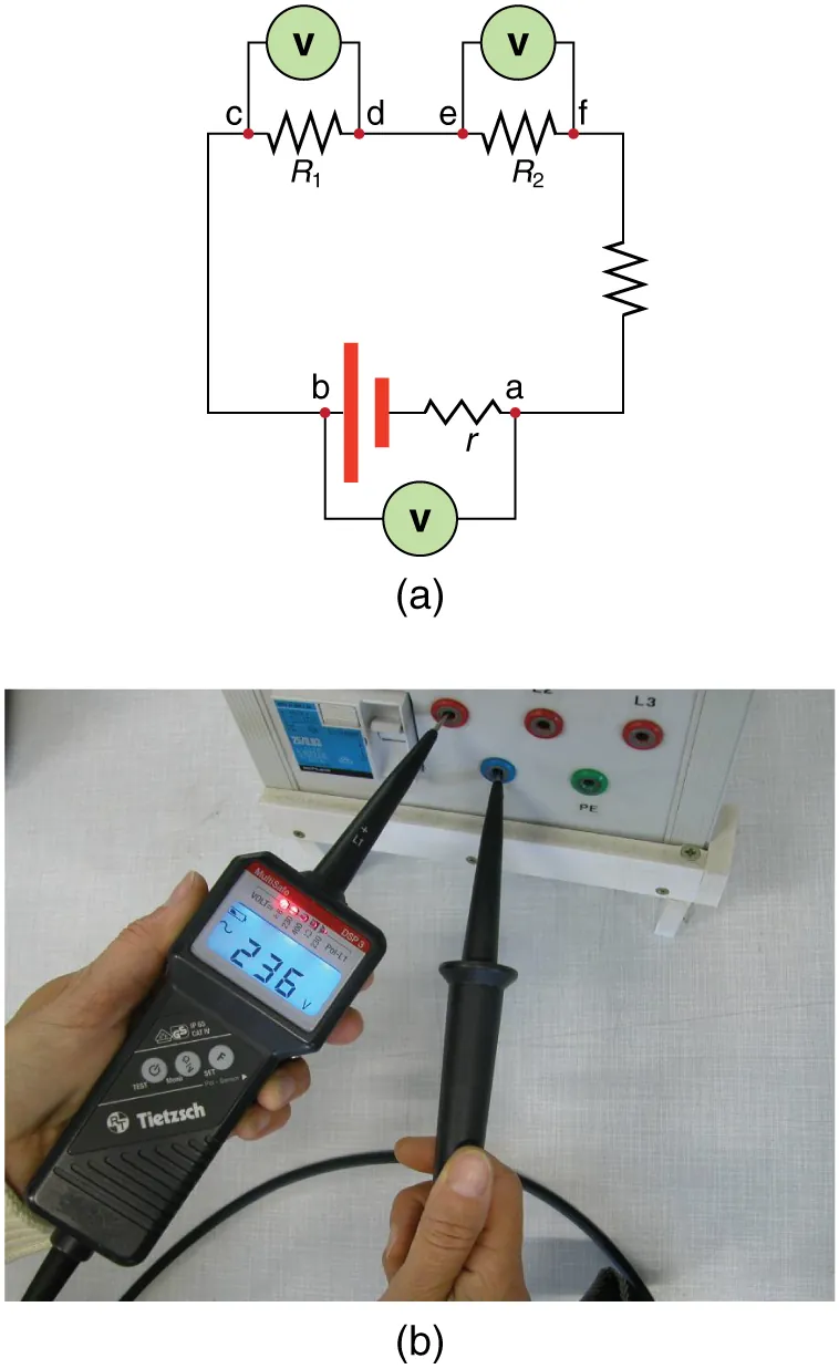
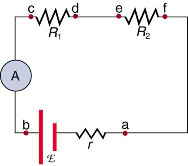
Schematic figures showing a voltmeter (V) connected in parallel across components and an ammeter (A) placed in series with the loop. Symbols align with standard practice for circuit diagrams. Note: the figure also includes internal resistance r and labelled nodes (a–b), which are minor extras beyond the syllabus focus. Source.
Resistive and Load Components
Resistors are fundamental in controlling current and voltage.
Fixed resistor: Rectangle or zigzag line.
Lamp (filament bulb): Circle containing a cross, indicating a glowing filament.
Heater: Symbolised as a resistor within a box, showing energy conversion to heat.
Resistance: The opposition to current flow, defined by the ratio of potential difference to current (R = V/I).
Loads such as lamps or heaters convert electrical energy to other forms—light or heat—and are essential for showing how circuits perform work.
Semiconductor Devices and Directional Components
Symbols for diodes and transistors indicate current direction and control functions:
Diode: Triangle pointing to a line; allows current in one direction only.
Light-emitting diode (LED): Diode symbol with outward-pointing arrows for emitted light.
Photodiode: Similar to an LED but with inward arrows representing received light.
For transistors, the symbols are more complex:
NPN transistor: Three terminals (emitter, base, collector) with an arrow on the emitter pointing out.
PNP transistor: Arrow on the emitter points in.
These symbols must always show the arrow direction, as it indicates conventional current flow. Misplacing or reversing arrows can alter the meaning entirely.
Ground, Fuses, and Protective Devices
Safety-related components are vital in circuit diagrams.
Earth (ground): Series of descending horizontal lines, representing connection to the planet’s conductive surface for safety.
Fuse: Small rectangle or line with a cross, denoting a safety device that melts if current exceeds a limit.
Circuit breaker: Switch symbol with an additional angled line, indicating automatic disconnection under fault conditions.
Such symbols highlight circuit protection mechanisms, preventing overheating and component damage.
Importance of Using Standard Symbols
The OCR specification emphasises standardisation as an integral part of scientific communication. Recognised symbols make circuit diagrams readable, safe, and reproducible.
When students design or analyse circuits:
Use standard IOP/BS symbols only.
Keep lines straight and orthogonal.
Label terminals or measurement points clearly if ambiguity might arise.
Avoid improvised or informal symbols, which may be penalised in exams.
Correct symbolic usage ensures that practical setups match the intended design, which is vital for achieving valid experimental results and maintaining safety standards in laboratory work.
Symbol Standards in Practice
In educational and professional contexts, adherence to symbol standards means that any trained physicist can interpret your diagram instantly. Standardised symbols are used:
In exam papers for consistent marking.
Across textbooks and data booklets for alignment with teaching materials.
Within engineering drawings, schematics, and simulation software (such as Multisim or Circuit Wizard).
By mastering these, OCR A-Level students ensure fluency in a universal graphical language central to all electrical and electronic analysis.
Practice Questions
Question 1 (2 marks)
(a) State two conventions that must be followed when drawing circuit diagrams using standard electrical symbols.
Question 1 (2 marks)
1 mark for stating that circuit diagrams must use recognised standard symbols (e.g. BS/IOP conventions).
1 mark for a diagramming convention, e.g. straight lines for wires, right angles at junctions, or clear labelling of components and terminals.
Question 2 (5 marks)
A student is asked to design a simple circuit diagram for an experiment to investigate the current–voltage relationship of a filament lamp.
The circuit must include:
a power supply,
a lamp,
an ammeter,
a voltmeter,
and a variable resistor.
(i) Draw or describe how the circuit should be arranged using correct standard electrical symbols.
(ii) Explain why the ammeter and voltmeter must be connected in different ways in the circuit.
(iii) Suggest one safety consideration when assembling the practical setup.
Question 2 (5 marks)
(i) (2 marks)
1 mark for indicating series connection of the power supply, lamp, ammeter, and variable resistor.
1 mark for showing or describing the voltmeter connected in parallel across the filament lamp only.
(ii) (2 marks)
1 mark for stating that the ammeter measures current and must be placed in series so all current flows through it.
1 mark for stating that the voltmeter measures potential difference and must be connected in parallel to measure across the component.
(iii) (1 mark)
1 mark for an appropriate safety precaution, e.g. limiting current to prevent the lamp overheating or using low voltage to avoid electric shock.
FAQ
Standardisation ensures that circuit diagrams are universally understood, reducing confusion across textbooks, laboratories, and industries.
International agreements, such as those from the International Electrotechnical Commission (IEC), establish a shared language of symbols. This consistency means students, engineers, and scientists can interpret and replicate circuits accurately anywhere in the world, promoting safety and precision.
For OCR A-Level Physics, following these conventions aligns school-level practice with professional engineering standards.
Earlier diagrams used hand-drawn or regional variants, such as zigzag resistors or non-standard lamp shapes.
Modern conventions use rectangular resistors, dots for junctions, and bridges for unconnected wires, following IEC and British Standards.
Updates were made to improve clarity when circuits are reproduced digitally, so OCR exam diagrams use the modern, clean-line version of these symbols. Recognising both types can help interpret older resources.
When two lines cross without a bridge, it may be mistaken for a junction, especially on low-resolution diagrams.
Using a bridge (small semicircle) makes it visually clear that no electrical connection exists.
This convention is critical in complex circuit diagrams, where numerous paths intersect. It prevents misinterpretation during circuit construction, ensuring accurate and safe experimental setups.
A schematic diagram uses standardised symbols to show how components are electrically connected, not their physical layout.
A pictorial diagram attempts to show what the actual setup looks like, including the component shapes and wiring positions.
In OCR A-Level Physics, schematics are always preferred because they communicate circuit logic, not appearance, and are consistent with how circuit analysis is performed.
Yes. Inaccurate or non-standard symbols can lead to two major issues:
Misinterpretation in practical work: A wrong symbol (e.g. diode drawn backwards) may cause incorrect circuit assembly or damage to components.
Loss of marks in exams: OCR mark schemes specifically reward correct use of recognised standard symbols.
Using proper symbols demonstrates understanding of both theory and safe experimental practice — essential for high-level credit.
