
OCR Specification focus:
‘Follow conventions: straight lines for wires, right angles at junctions, labels where needed.’
Clear, accurate circuit diagrams are essential for effective communication in physics, ensuring electrical circuits are represented consistently and safely across practical work, examinations, and professional scientific documentation.
The Purpose of Circuit Diagram Conventions
Circuit diagrams are schematic representations that show how electrical components connect within a system. They replace physical components with standardised symbols and are used universally to communicate circuit design efficiently. The OCR specification emphasises that clarity, precision, and standardisation are central to producing correct circuit diagrams for A-Level Physics and beyond.
Good practice in diagramming ensures that circuits are easy to read, free of ambiguity, and accurately convey electrical relationships. The OCR specification emphasises that clarity, precision, and standardisation are central to producing correct circuit diagrams for A-Level Physics and beyond.
Good diagramming habits not only make interpretation simpler but also promote safe assembly of circuits during experimental work. Misunderstood or unclear diagrams can lead to wiring errors, component damage, or inaccurate results.
Fundamental Principles of Good Diagramming
Straight Lines for Wires
One of the most fundamental conventions in circuit drawing is that connecting wires must be represented by straight lines. Straight lines communicate a clear, unbroken path for current flow and minimise visual clutter. Avoiding curved or diagonal connections prevents confusion, particularly when multiple wires run parallel or cross each other.
Always use horizontal and vertical lines to connect components.
Keep line spacing uniform across the diagram.
Ensure that line intersections are handled consistently (see below).
When drawing by hand, use a ruler or grid paper to maintain straightness; when using software, rely on snapping tools to maintain orthogonality.
Right Angles at Junctions
Junctions occur where two or more wires meet or branch. The OCR guidance specifies that wires should meet at right angles, not diagonally. This makes the diagram geometrically clear and visually structured.
A T-junction should be drawn with a single right-angle connection, clearly showing where the circuit divides.
Avoid unnecessary acute or obtuse angles, as these may be mistaken for wire crossings or separate loops.
Junction: A point in a circuit diagram where two or more conductors connect, allowing current to divide or combine.
Distinguishing Crossings and Connections
A frequent source of confusion is the distinction between wires that cross and those that connect. Good practice requires clear visual cues:
Connected wires are shown with a solid dot (•) at the point of intersection.
Unconnected wires simply cross without a dot or, alternatively, one wire may be shown as a bridge (semi-circle) over the other.
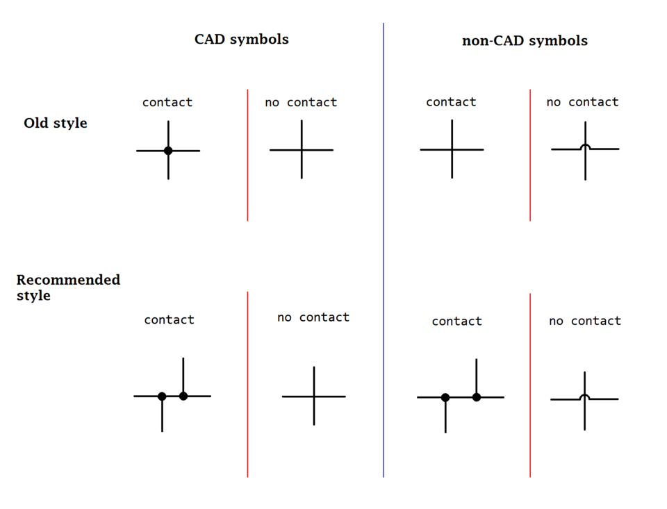
This diagram contrasts modern conventions for showing connected wires (with a solid node) and unconnected crossings (without a node or with a small “bridge”). Using these conventions prevents misreading at intersections and is recommended for uncluttered, unambiguous schematics. The content exactly matches the level required for OCR A-Level practice. Source.
Maintaining this distinction ensures that the electrical topology is unambiguous to anyone reading the circuit.
Layout and Component Positioning
Logical Flow of Current
Arrange the diagram so that current appears to flow from left to right, or from top to bottom, following conventional current direction (from positive to negative). This mirrors written and reading direction, improving comprehension.
Power sources (cells or batteries) are usually placed on the left-hand side.
Loads (resistors, lamps, or devices) follow in the middle.
Measuring instruments (voltmeters, ammeters) and switches are placed logically according to their function.

A minimal schematic of a battery, a switch, and a lamp drawn with straight orthogonal wiring. The layout reinforces left-to-right flow and maintains generous spacing for legible labels. This is an exemplar of neat, OCR-appropriate diagramming. Source.
Component Spacing and Alignment
Maintain consistent spacing between symbols to avoid visual crowding. Components should align neatly along straight wires where possible.
Avoid overlapping symbols.
Keep labels close to their symbols without touching lines.
Use grid alignment for uniformity in digital drawings.
This discipline reflects professional engineering practice and allows others to replicate the circuit reliably.
Labelling and Annotations
Clear and Consistent Labels
Labelling is essential when circuits include multiple similar components or sensors. The OCR specification explicitly requires labels where needed. Each symbol should be easily identifiable with either a component name, variable symbol, or measurement point.
Examples include:
R₁, R₂, R₃ for multiple resistors.
V₁, V₂ for voltmeters or measured potentials.
SW₁ for switches in multi-control circuits.
Directional Indicators
In complex circuits, arrows can be added to indicate current direction or component polarity. For instance:
Diodes must include a clear arrow and bar symbol to show conduction direction.
Transistors and LEDs require orientation markers to show emitter, base, and collector or light emission direction.
Polarity: The orientation of a component or voltage indicating positive and negative terminals, determining current direction through it.
Reference Values and Units
Where applicable, add numerical information directly beside components to support quantitative analysis. For instance:
Resistors: “100 Ω” or “Variable 0–10 kΩ”
Power sources: “12 V”
Capacitors: “100 µF”
Use standard SI units and always write units clearly. Avoid mixing unit prefixes (e.g., writing 0.001 kΩ instead of 1 Ω).
Visual Consistency and Neatness
Line Weight and Symbol Clarity
A clear diagram uses consistent line thickness and symbol proportion. Heavy or uneven lines can obscure junctions, while faint lines may be hard to read in print. When using computer tools, select a medium line weight that prints clearly on A4 paper.
Ensure all component symbols are drawn using the official OCR and IEC (International Electrotechnical Commission) standards, maintaining recognised proportions.
Avoiding Ambiguity
Every symbol and connection should be unambiguous at a glance. Avoid overlapping or incomplete symbols, and never let wires pass through components unless clearly intended. When multiple loops or branches exist, maintain symmetry to aid tracing of circuit paths.
A well-structured diagram not only satisfies OCR marking criteria but also demonstrates professional attention to detail expected in laboratory work.
Good Practice in Digital and Hand-Drawn Circuits
Hand-Drawn Diagrams
When sketching circuits in laboratory books or exam conditions:
Use a sharp pencil and ruler.
Keep symbols proportionate and evenly spaced.
Write labels in uppercase letters for clarity.
Check all connections for completeness before use.
Computer-Aided Diagramming
Digital tools (e.g., circuit simulators or drawing software) provide features for automatic alignment and symbol libraries. Follow these best practices:
Use only standard symbol libraries approved for A-Level physics.
Avoid decorative or non-standard icons.
Export diagrams at sufficient resolution to preserve readability when printed.
Digital diagrams must still follow all conventional layout principles — straight lines, right angles, and appropriate labels — exactly as for hand-drawn versions.
The Role of Clarity in Safety and Communication
Clear diagramming is not merely aesthetic; it supports safety and effective scientific communication. During experiments, an unclear diagram can cause mis-wiring or short circuits. In written reports, clarity ensures that others can reproduce your circuit accurately, a central tenet of scientific validity. The OCR requirement to “follow conventions” therefore underlines both practical competence and professional responsibility in physics.
Practice Questions
Question 1 (2 marks)
A student sketches a circuit diagram in which wires are drawn diagonally between components, and a crossing of two wires has no connecting dot.
(a) State one improvement the student should make to follow good practice in circuit diagramming.
(b) Explain why this improvement is important.
Mark Scheme:
(a) 1 mark for identifying an improvement:
Use straight horizontal and vertical lines instead of diagonal connections (1)
OR include a dot at wire junctions to show connection clearly (1)
(b) 1 mark for explanation:
Ensures the diagram is easy to interpret and avoids confusion between connected and unconnected wires (1)
Question 2 (5 marks)
Figure 1 shows part of a circuit diagram drawn by a student. The diagram uses curved lines for wires, some components overlap, and several labels are missing.
(a) Describe three aspects of good practice that the student should apply to improve this circuit diagram.
(b) Explain how following these conventions improves clarity and safety when constructing or analysing the circuit.
Mark Scheme:
(a) Up to 3 marks for identifying correct aspects of good practice (any three):
Use straight, horizontal and vertical lines for all connecting wires (1)
Join wires at right angles rather than diagonally (1)
Add solid dots to indicate electrical junctions and omit them where wires merely cross (1)
Keep symbols evenly spaced and aligned to prevent overlap (1)
Clearly label each component (e.g., R1, V1, SW1) (1)
(b) Up to 2 marks for explanation of benefits:
Improves readability and interpretation by others (1)
Reduces likelihood of wiring mistakes or short circuits during practical construction (1)
Promotes professional and standardised communication of circuit design (1, max 2 marks for section)
FAQ
Right angles make a circuit’s layout immediately recognisable and consistent with standardised schematic conventions. Diagonal or curved lines can distort the geometry and make it harder to trace current paths.
Using horizontal and vertical wires:
Improves alignment and spacing of components.
Makes junctions and branches easier to identify.
Prevents confusion when diagrams are copied, printed, or redrawn digitally.
This convention mirrors industry and examination standards, ensuring your diagrams are readable and professional.
When more than two wires connect at one point, a single, solid dot should be drawn clearly at the intersection.
Best practice includes:
Keeping all wires meeting at the same spot, not slightly offset.
Drawing wires at 90° angles wherever possible.
Avoiding excessive connections in one location; if the diagram becomes cluttered, consider redrawing with separate junctions.
This helps examiners and technicians easily distinguish genuine circuit nodes from accidental wire crossings.
A schematic diagram represents the logical structure of a circuit using standardised symbols, while a pictorial diagram shows how components physically appear.
Key distinctions:
Schematic: prioritises electrical relationships and current flow; ideal for problem-solving and communication.
Pictorial: focuses on component appearance and layout; useful for beginners or assembly guides.
In A-Level Physics, schematic diagrams are always preferred because they allow clear analysis of voltage, current, and resistance relationships.
When using software or word processors:
Maintain consistent line thickness and font size.
Use snap-to-grid features to keep components aligned.
Export diagrams in vector formats (SVG, PDF) to avoid blurriness.
Avoid colour overuse; black or grey lines maintain clarity when printed.
Readable diagrams communicate accuracy and professionalism — both important for high-quality coursework and lab reports.
Students often lose marks for poor presentation or misinterpretation, not incorrect physics.
Frequent errors include:
Missing or misplaced connection dots at wire junctions.
Overlapping symbols or labels.
Inconsistent use of right angles or straight lines.
Incorrect or missing component symbols.
Failure to indicate direction or polarity where relevant.
Following the OCR conventions ensures the diagram conveys both scientific understanding and technical precision, earning full marks for clarity and accuracy.
