
OCR Specification focus:
‘For series resistors, total resistance R = R₁ + R₂ + … .’
Understanding total resistance in series circuits is essential in electrical physics. It allows accurate prediction of current and voltage behaviour when multiple resistive components are connected end-to-end.
Total Resistance in Series Circuits
When resistors are connected in series, they are arranged end-to-end so that the same current flows through each resistor sequentially. This configuration is commonly used in circuits where a uniform current is required across all components but a cumulative voltage drop occurs across each element.

Series circuit with three resistors and a DC source. The diagram highlights the single current path characteristic of series connections. Labels make it clear which elements are in series; no extra theory beyond the syllabus is included. Source.
Key Characteristics of Series Circuits
Single Path for Current: The same current passes through each component, as there is only one conducting path.
Shared Voltage: The total potential difference across the series combination equals the sum of potential differences across each resistor.
Energy Distribution: Each resistor converts electrical energy into heat proportionally to its resistance and the square of the current, according to Joule’s law.
These characteristics make series arrangements useful in applications such as current-limiting devices and voltage dividers when equal current is desired through all components.
Understanding Resistance in Series
Resistance is a measure of how much a component opposes the flow of electric current. When resistors are connected in series, the total resistance increases because the current must pass through each resistor in turn, encountering each resistance sequentially. The combined effect is an additive total resistance.
Resistance: The opposition that a component offers to the flow of electric current, measured in ohms (Ω).
In series, resistances add directly because the current remains constant while potential differences accumulate across each resistor.
The Series Resistance Equation
EQUATION
—-----------------------------------------------------------------
Total Resistance in Series (R_total) = R₁ + R₂ + R₃ + …
R_total = Total resistance of all components in series, in ohms (Ω)
R₁, R₂, R₃ = Individual resistances of each resistor, in ohms (Ω)
—-----------------------------------------------------------------
This relationship derives directly from Ohm’s law, which states that the potential difference across a resistor equals the product of the current through it and its resistance (V = IR).
For resistors in series, since current is constant and voltages add, the equivalent resistance is simply the algebraic sum of all individual resistances.
Deriving the Series Resistance Relationship
Consider a series circuit with resistors R₁, R₂, and R₃ connected to a source of electromotive force (e.m.f.) E.
According to Ohm’s law, the potential difference across each resistor is:
V₁ = I × R₁
V₂ = I × R₂
V₃ = I × R₃
The total potential difference (V_total) across the combination is the sum:
V_total = V₁ + V₂ + V₃
Substituting the above expressions:
V_total = I(R₁ + R₂ + R₃)
Since V_total = I × R_total, it follows that:
R_total = R₁ + R₂ + R₃
This confirms that resistances in series add directly. Each resistor contributes linearly to the total opposition in the circuit.
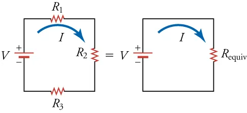
Figure 19.14 shows a series chain of three resistors alongside its equivalent single resistor with the same resistance and current. This visual underpins the equation R_total = R₁ + R₂ + R₃. The figure includes only concepts used in your notes; no additional subtopics are introduced. Source.
Relationship to Kirchhoff’s Second Law
The principle governing this addition of resistances aligns with Kirchhoff’s Second Law, which states that the sum of electromotive forces (e.m.f.s) in a closed loop equals the sum of potential drops across the components in that loop.
In a series circuit, as current is identical through all components, the total potential drop across all resistors equals the supply e.m.f., confirming that:
E = V₁ + V₂ + V₃ + …
This reinforces the mathematical relationship for total resistance. Kirchhoff’s law therefore provides a theoretical foundation for understanding how and why the potential differences combine linearly in a series network.
Practical Applications and Circuit Behaviour
1. Voltage Division
In a series circuit, each resistor experiences a voltage drop proportional to its resistance value. A higher resistance draws a larger share of the total voltage. This concept is central to potential divider circuits, though those are studied in later sections.
2. Current Control
By increasing the total resistance, the circuit current can be reduced for a fixed supply voltage. This is often used in protecting sensitive components from excessive current flow.
3. Energy Distribution
Because each resistor dissipates power as heat (P = I²R), the total power loss in a series circuit equals the sum of the individual power dissipations. The resistor with the highest resistance will dissipate the greatest energy per second.
4. Dependence on Component Tolerances
In practical circuits, resistor tolerances affect the accuracy of total resistance. For example, using three 100 Ω resistors each with ±5% tolerance could result in total resistance varying from 285 Ω to 315 Ω. This becomes significant in precision measurement and calibration circuits.
Experimental Verification of Total Resistance in Series
To experimentally confirm the relationship R_total = R₁ + R₂ + …, one can measure the total current through a series combination and the total potential difference across it.
Procedure Overview:
Connect resistors in series with a variable power supply and ammeter in series, and a voltmeter across the combination.
Measure the current for several applied voltages.
Calculate total resistance using R_total = V_total / I.
Compare with the sum of the individually measured resistances obtained using an ohmmeter.
Expected Outcome:
The measured total resistance should equal the arithmetic sum of the individual resistances, within experimental uncertainty. Minor deviations can occur due to lead resistances and measurement errors.
Important Considerations
Uniform Current: Since the current is identical throughout, any change in one resistor affects the potential distribution across the rest of the circuit.
Open Circuit Effects: If one resistor fails (open circuit), the entire series current path breaks, and no current flows through the circuit.
Temperature Effects: Resistance of components may increase with temperature, especially in metallic resistors, affecting total resistance during prolonged operation.
Instrument Loading: Using low-resistance measuring instruments in series can slightly alter the circuit resistance, so instruments should be chosen carefully.
Summary of Key Relationships
In a series circuit, current is the same through all components.
The potential difference across the entire circuit equals the sum of individual voltage drops.
The total resistance equals the sum of all resistances:
R_total = R₁ + R₂ + R₃ + …
This relationship is consistent with Kirchhoff’s Second Law and Ohm’s Law principles.
Practice Questions
Question 1 (2 marks)
Three resistors of resistances 4.0 Ω, 6.0 Ω, and 10.0 Ω are connected in series.
Calculate the total resistance of the combination.
Mark scheme:
Correct use of formula R_total = R₁ + R₂ + R₃ (1 mark)
Correct total resistance R_total = 20.0 Ω (1 mark)
Question 2 (5 marks)
A circuit consists of a 12 V d.c. supply connected to three resistors in series: 2.0 Ω, 3.0 Ω, and 5.0 Ω.
(a) Calculate the total resistance of the circuit. (1 mark)
(b) Determine the current flowing through the circuit. (2 marks)
(c) Calculate the potential difference across the 5.0 Ω resistor. (2 marks)
Mark scheme:
(a)
Correct use of series resistance formula: R_total = 2.0 + 3.0 + 5.0 (1 mark)
→ R_total = 10.0 Ω
(b)
Correct use of Ohm’s law: I = V / R_total (1 mark)
Substitution: I = 12 / 10.0 = 1.2 A (1 mark)
(c)
Recognition that the same current flows through all resistors in series (1 mark)
Correct calculation: V = I × R = 1.2 × 5.0 = 6.0 V (1 mark)
FAQ
In a series circuit, the same current must pass through each resistor sequentially. Every resistor offers opposition to current flow, so the total effect is cumulative.
The charge carriers lose energy as they pass through each resistor, resulting in an increasing potential drop along the circuit. Adding another resistor adds another region of opposition, increasing the overall resistance the current experiences.
Thus, total resistance increases because the resistors act as a continuous chain of energy-dissipating components.
Each resistor has a manufacturing tolerance, typically expressed as a percentage (e.g., ±5%). When resistors are connected in series, their total resistance can vary depending on whether individual components are above or below their nominal values.
For instance:
If all resistors are at their upper limit, the total resistance will be higher than calculated.
If all are at the lower limit, it will be lower.
This variability can cause small but significant deviations in expected current or voltage in precision applications.
If a single resistor fails open (creates a break in continuity), the circuit becomes incomplete, and no current can flow.
In series circuits, there is only one path for current; any interruption stops the entire flow. This is why devices connected in series—such as decorative light strings—fail entirely if one component is damaged.
The failure behaves like adding infinite resistance, resulting in a total current of zero throughout the circuit.
Wires and connections have small but non-zero resistances. When measuring total resistance in a circuit, these can add to the expected value, especially if the resistors themselves are of low resistance.
To minimise this:
Use short, thick connecting wires.
Employ four-wire (Kelvin) measurement techniques for precision.
Subtract known lead resistances from total readings.
These effects are particularly relevant when determining internal resistance or verifying theoretical circuit calculations
Because there is only one continuous conducting path, charge cannot accumulate or disappear between resistors. The rate of charge flow (current) entering one resistor must equal that leaving it.
This is consistent with Kirchhoff’s First Law, which states that current is conserved at any junction.
Although the potential difference across each resistor varies depending on its value, the current remains constant throughout, ensuring energy conservation across the entire loop.
