
OCR Specification focus:
‘Analyse circuits containing both series and parallel components and sources.’
Understanding mixed component circuit analysis is essential for mastering practical and theoretical circuit problems. These circuits combine both series and parallel arrangements, requiring systematic use of Kirchhoff’s laws.
Understanding Mixed Component Circuits
A mixed component circuit includes elements connected both in series and in parallel within the same network. Such circuits are common in real-world applications, where different components require different current or voltage conditions.
Key Characteristics
Contain multiple paths for current flow due to parallel sections.
Have shared current in series components and shared voltage in parallel components.
Require careful analysis using Kirchhoff’s first and second laws to determine current, potential difference (p.d.), and resistance at various points.
Kirchhoff’s Laws in Mixed Circuits
Mixed component circuit analysis depends on two foundational rules that describe the conservation of charge and energy in electrical systems.
Kirchhoff’s First Law – Current Rule
Kirchhoff’s First Law: The sum of currents entering a junction equals the sum of currents leaving it, reflecting the conservation of electric charge.
This law allows the determination of unknown currents in branches of parallel sections. For a given junction:
I₁ + I₂ + I₃ (incoming) = I₄ + I₅ (outgoing)
Each branch current can be expressed in terms of known or measured quantities, simplifying circuit analysis.
Kirchhoff’s Second Law – Voltage Rule
Kirchhoff’s Second Law: In any closed loop, the sum of electromotive forces (emfs) equals the sum of potential drops (voltages across resistors and components).
This expresses energy conservation within the loop.
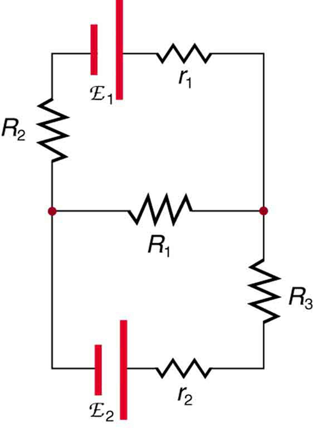
A labelled multi-loop circuit with resistors R₁–R₅ and two sources V₁ and V₂. The diagram illustrates junctions and overlapping loops typical of mixed series–parallel networks that require Kirchhoff’s rules. Note: internal resistances r₁ and r₂ appear here as an extra detail not required by the sub-subtopic but do not change the loop-equation method. Source.
The total energy supplied by sources equals the total energy dissipated or stored within the loop’s elements.
Resistance in Mixed Circuits
Accurately determining total resistance is key to analysing mixed component networks. The circuit can be broken down stepwise using the rules for series and parallel resistors.
Series Sections
EQUATION
—-----------------------------------------------------------------
Total Resistance in Series (R_total) = R₁ + R₂ + R₃ + …
R = Resistance of each component (Ω)
—-----------------------------------------------------------------
Parallel Sections
EQUATION
—-----------------------------------------------------------------
Total Resistance in Parallel (1/R_total) = 1/R₁ + 1/R₂ + 1/R₃ + …
R = Resistance of each branch (Ω)
—-----------------------------------------------------------------
These equations enable simplification of parts of a complex circuit before recombining them. The overall resistance is often less than any individual resistor when parallel sections are included.
Step-by-Step Circuit Analysis Method
Analysing mixed component circuits systematically prevents errors and ensures all current and voltage relationships are accounted for.
Step 1: Identify Series and Parallel Components
Trace the circuit diagram carefully, labelling each resistor and node.
Determine which components share the same current (series) and which share the same voltage (parallel).
Step 2: Simplify in Stages
Replace series and parallel combinations with their equivalent resistances.

A DC series–parallel circuit with labelled elements illustrating how parallel branches sit in series with other components. The layout is ideal for demonstrating step-wise reduction to an equivalent resistance before back-calculating branch currents and p.d.s. Labels are minimal and clear, matching A-level expectations. Source.
Redraw the circuit after each simplification step to maintain clarity.
Continue until a single total resistance is found.
Step 3: Calculate Total Current
Using Ohm’s law, find the total current from the supply.
EQUATION
—-----------------------------------------------------------------
Ohm’s Law (I) = V / R
I = Current (A)
V = Potential difference (V)
R = Total resistance (Ω)
—-----------------------------------------------------------------
This step gives the total current flowing from the source before distributing it through various branches.
Step 4: Apply Kirchhoff’s Laws
Use Kirchhoff’s first law at junctions to find unknown branch currents.
Apply Kirchhoff’s second law around loops to determine potential differences.
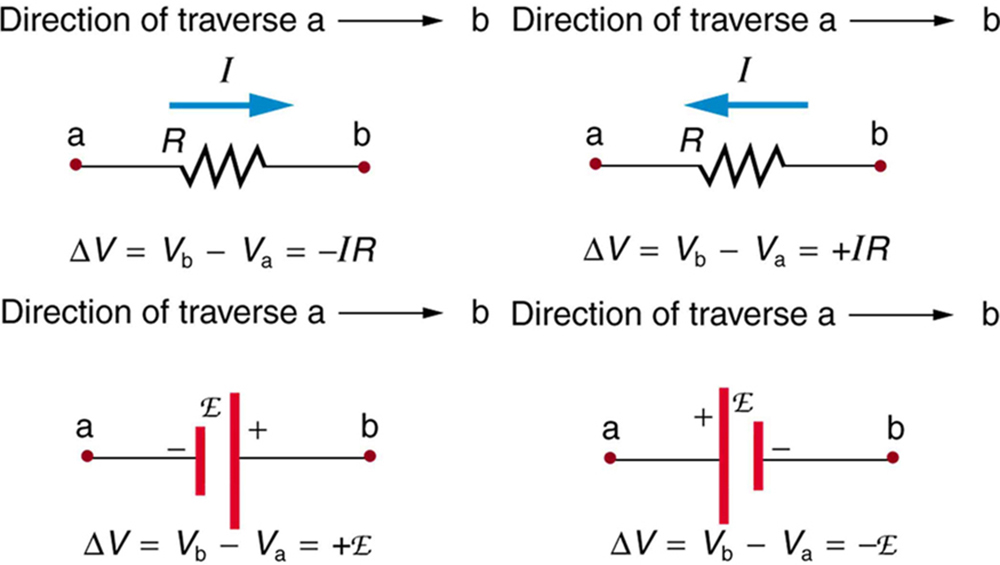
Four panels illustrate the voltage change when moving across a resistor with/against current and across a source from − to + or + to −. These conventions ensure consistent signs in Kirchhoff’s loop equations. The presentation is minimal, reinforcing method rather than numeric detail. Source.
Check that the sum of voltages equals the total emf in every closed loop.
Step 5: Back-Calculate Quantities
Determine current and voltage in individual components by reversing the simplification process.
For series resistors, current is the same through each, but voltages divide according to resistance ratios.
For parallel resistors, voltage is the same, but current divides inversely to resistance.
Power Distribution and Energy Considerations
Each resistor or component dissipates energy according to power relations, which are useful for checking results and understanding circuit behaviour.
EQUATION
—-----------------------------------------------------------------
Power (P) = I × V = I²R = V² / R
P = Power dissipated (W)
I = Current through component (A)
V = Potential difference across component (V)
R = Resistance (Ω)
—-----------------------------------------------------------------
By comparing the total supplied and dissipated power, one can confirm energy conservation in the system.
Multiple Loops and Junctions
In mixed circuits, more than one closed loop often exists. Each loop may contain resistors, sources of emf, or shared junctions with other loops.
Loops are analysed individually using Kirchhoff’s second law.
Equations are established for each loop, representing energy conservation.
Solving simultaneous equations provides unknown currents and voltages.
The process may involve algebraic substitution or matrix methods for larger circuits, ensuring consistent current directions and sign conventions throughout.
Practical Insights and Testing
Mixed component circuits frequently appear in laboratory and real-world contexts such as household wiring or sensor networks.
To confirm theoretical analysis:
Measure current using ammeters in series with branches.
Measure voltage across components using voltmeters in parallel.
Compare experimental readings with predicted values.
Be mindful of instrument resistance, as this can cause slight deviations in measured results. Digital meters with high input impedance minimise errors.
Common Errors and Best Practices
When analysing mixed component circuits:
Maintain consistent current direction conventions in all loops.
Use clear circuit diagrams with labelled nodes and junctions.
Re-check series and parallel identifications after simplifications.
Confirm the sum of currents at each junction and sum of voltages in each loop satisfy Kirchhoff’s laws.
These practices ensure accurate results and reinforce understanding of the fundamental conservation principles underlying electrical circuit behaviour.
Practice Questions
Question 1 (2 marks)
A resistor of resistance 4.0 Ω is connected in series with a 6.0 Ω resistor. This combination is then connected in parallel with a 12 Ω resistor.
Calculate the total resistance of the circuit.
Mark scheme:
Correct calculation of total resistance for the series pair (4.0 + 6.0 = 10.0 Ω) – 1 mark
Correct use of the parallel formula 1/R = 1/10 + 1/12 and final answer R = 5.45 Ω (or 5.4 Ω to 2 s.f.) – 1 mark
Question 2 (5 marks)
A circuit contains two resistors, R1 = 8.0 Ω and R2 = 12 Ω, connected in parallel across a 9.0 V battery of negligible internal resistance. A third resistor, R3 = 5.0 Ω, is connected in series with this parallel combination.
(a) Calculate the total resistance of the circuit. (2 marks)
(b) Determine the total current supplied by the battery. (1 mark)
(c) Calculate the current in each resistor. (2 marks)
Mark scheme:
(a)
Correct calculation of parallel resistance: 1/Rp = 1/8 + 1/12 → Rp = 4.8 Ω – 1 mark
Correct addition of series resistor: Rtotal = 4.8 + 5.0 = 9.8 Ω – 1 mark
(b)
Correct use of Ohm’s law: I = V / Rtotal = 9.0 / 9.8 = 0.92 A – 1 mark
(c)
Voltage across parallel network: Vp = 0.92 × 4.8 = 4.42 V – 1 mark
Current in each parallel branch:
I1 = 4.42 / 8.0 = 0.55 A, I2 = 4.42 / 12 = 0.37 A – 1 mark
(Allow answers within acceptable rounding tolerance.)
FAQ
Simplifying a mixed circuit into equivalent resistances before applying Kirchhoff’s laws reduces algebraic complexity and minimises potential errors.
By first combining series and parallel resistors into simpler forms, students can:
Identify total resistance and overall current more easily.
Apply Kirchhoff’s laws only to the remaining loops and junctions, rather than the entire complex network.
This step-by-step method also helps visualise how current and potential difference distribute throughout different sections of the circuit.
In parallel branches of a mixed circuit, each branch experiences the same potential difference because both ends connect directly to the same two nodes.
However, the current divides among branches based on their resistances:
Lower resistance → higher current.
Higher resistance → lower current.
This relationship ensures energy conservation while maintaining equal voltage across each branch.
Adding another branch in parallel provides an additional path for current to flow, effectively reducing the total resistance of the circuit.
When total resistance decreases, the overall current supplied by the source increases (assuming constant emf).
However, the voltage across existing branches remains unchanged, meaning branch currents must readjust to maintain Kirchhoff’s first law at each junction.
Consistent sign convention is vital for writing correct loop equations.
When traversing a loop:
Voltage rises (positive) occur when moving from the negative to positive terminal of a source.
Voltage drops (negative) occur when moving in the direction of current through a resistor.
Choosing one direction—clockwise or anticlockwise—for loop traversal and sticking with it prevents sign confusion when solving for unknown currents and potential differences.
Measurement inaccuracies can distort current and voltage readings, affecting calculated resistances and Kirchhoff’s law verification.
Common sources of error include:
Ammeter and voltmeter internal resistance altering circuit conditions.
Loose or oxidised connections causing fluctuating readings.
Heating of resistors changing resistance slightly over time.
Minimising these effects involves using digital meters with high sensitivity, maintaining stable connections, and allowing components to cool between measurements.
