
OCR Specification focus:
‘Use magnetic field lines to represent and map magnetic fields.’
Magnetic field lines provide a visual and conceptual model of invisible magnetic fields, helping illustrate field strength, direction, and spatial behaviour in natural and engineered systems.
Understanding Magnetic Field Lines
Magnetic fields are regions where magnetic materials or moving charges experience forces. To represent these regions clearly, physicists use magnetic field lines, which illustrate both the direction and relative strength of the magnetic field at different points in space.
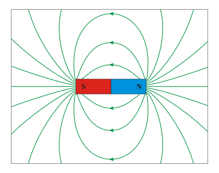
Field lines around a bar magnet. The arrows show the direction of the magnetic field from the north pole to the south pole outside the magnet, with lines denser near the poles where the field is strongest. This diagram illustrates the standard conventions for drawing and interpreting magnetic field lines. Source.
When this representation is applied consistently, it provides a powerful tool for analysing the behaviour of permanent magnets, current-carrying conductors, and magnetic devices. Field lines are conceptual rather than physical, yet they follow strict conventions that ensure accurate visualisation.
Key Properties of Magnetic Field Lines
Magnetic field lines follow several fundamental rules that help maintain clarity and consistency:
They emerge from the north pole of a magnet and curve around to enter the south pole.
They form closed loops, continuing inside the magnet from south back to north.
They never cross, as this would imply two directions for the magnetic field at one point.
Where lines are closer together, the field is stronger; where they are spread out, the field is weaker.
Their direction at any point shows the direction a free north pole would move.
These properties ensure that diagrams reflect the true behaviour of magnetic fields.
Representing Field Direction
The direction of a magnetic field is vital for predicting how magnetic forces act on currents and charges. Field lines provide an intuitive visual cue for this direction.
Arrow Conventions
The arrows drawn on magnetic field lines indicate the direction from the north to the south pole outside the magnet. This makes directional relationships easier to identify when analysing field interactions.
A region where arrows align and maintain uniform spacing signifies a uniform magnetic field, which is frequently encountered between the poles of a strong horseshoe magnet or inside certain electromagnetic devices.
Mapping Magnetic Fields
Mapping magnetic fields involves identifying the shape and density of field lines around magnets or electrical conductors. This process is important in developing an accurate understanding of how fields behave in practical contexts and supports later topics such as forces on currents and motion of charged particles.
Techniques for Mapping Fields
Students typically use methods that reveal the hidden magnetic structure using simple equipment:
Iron filings
When sprinkled on a sheet of paper placed over a magnet, iron filings align along the magnetic field lines. This technique produces a clear visual outline of the field pattern.Compass plotting
A small plotting compass, placed at multiple points around a magnet, indicates the direction of the magnetic field. Marking each compass orientation and connecting the directional arrows provides a reliable mapping of the field.
These methods enhance understanding by making magnetic fields visible and measurable.
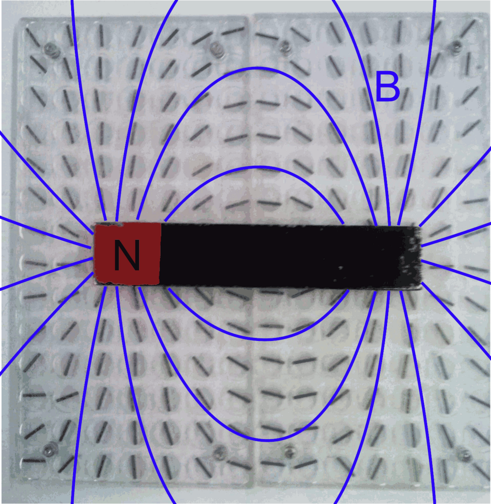
Bar magnet on a compass board with field lines drawn in. Each small compass aligns with the local magnetic field, and the smooth curve through their directions traces a field line. This image directly illustrates how plotting compasses can be used to map magnetic fields in a school laboratory. Source.
Field Line Patterns for Common Magnetic Sources
Although the syllabus subsubtopic focuses on field lines and mapping, recognising typical patterns helps reinforce why conventions for drawing lines matter.
Bar Magnet Field Patterns
A single bar magnet has a distinctive pattern:
Lines curve outward from the north pole.
They loop symmetrically into the south pole.
The densest region of lines appears near the poles, showing where the field is strongest.
This symmetry and density distribution are central features students must be able to identify when mapping a field.
Multiple Magnet Arrangements
Mapping becomes especially useful when examining how fields combine:
Like poles facing each other create a region of weak field between them, pushing field lines outward.
Unlike poles facing each other produce a strong, near-uniform field in the gap, with straight, parallel field lines between the poles.
Understanding these combinations supports the development of spatial reasoning about magnetic interactions.
Uniform and Non-Uniform Fields
A clear distinction exists between uniform and non-uniform magnetic fields. Students benefit from recognising this visually in field diagrams.
Uniform Fields
A uniform magnetic field has:
Parallel, equally spaced field lines
Constant field strength and direction throughout the region
Such fields are essential in applications including velocity selectors and cathode ray tubes, although detailed study of these devices occurs in later subtopics.
Non-Uniform Fields
Non-uniform fields show changing spacing and direction of field lines. These commonly arise around bar magnets, coils, and irregular magnetic structures. Mapping is particularly valuable in identifying these variations.
Importance of Field Line Representations
Magnetic field line diagrams serve as the foundation for more advanced topics such as electromagnetic forces, induction, and applications in motors and generators. Accurate field mapping ensures a deeper understanding of how magnetic phenomena operate on currents, charges, and circuits.
Uses of Field Line Diagrams
Illustrating regions of strong and weak field
Determining the direction of magnetic forces
Designing and evaluating magnetic devices
Supporting predictions in problem-solving situations
These representations transform an invisible physical quantity into an accessible visual model, helping students develop conceptual fluency essential for later study.
Practical Skills in Field Mapping
Students should be confident in producing clear field maps using standard techniques. Effective diagrams follow conventions precisely and reflect the behaviours described in the specification.
Good Practice in Field Mapping
Begin mapping at the poles or most significant regions.
Use smooth curves for field lines, avoiding sharp corners.
Ensure line spacing reflects changes in field strength.
Include directional arrows consistently and clearly.
By mastering these techniques, students gain robust skills that support their wider understanding of electromagnetism.
Practice Questions
Question 1 (2 marks)
A student places a sheet of paper over a bar magnet and gently sprinkles iron filings onto it.
(a) Describe what the pattern of iron filings shows about the magnetic field around the bar magnet.
(b) State one rule that magnetic field lines must follow when being drawn.
Question 1 (2 marks)
(a)
• Iron filings form curved patterns showing the shape of the magnetic field around the magnet (1)
• Filings are densest near the poles, indicating stronger field there (1 max)
(b)
• Field lines never cross / Field lines go from north to south outside the magnet / Field lines form closed loops (1)
Question 2 (5 marks)
A teacher gives a group of students a bar magnet and a small plotting compass.
(a) Describe in detail how the students can use the plotting compass to map the magnetic field around the bar magnet.
(b) Explain how the resulting diagram can be used to determine both the direction and relative strength of the magnetic field in different regions around the magnet.
Question 2 (5 marks)
(a)
• Place the plotting compass at a point near the magnet and allow it to settle so its needle aligns with the magnetic field (1)
• Mark the direction the compass needle points on the paper (1)
• Move the compass to a new nearby position and repeat the process to build up a series of directional marks (1)
• Draw smooth curves through the marks to create field lines (1 max)
(b)
• Direction of arrows on the drawn field lines indicates the direction of the magnetic field (north to south outside the magnet) (1)
• Spacing of the field lines shows field strength: closer lines represent a stronger magnetic field, wider spacing a weaker field (1)
FAQ
Magnetic field lines are a conceptual tool, so the number drawn is a choice made for clarity rather than a physical quantity. The aim is to show the pattern and strength without overcrowding the diagram.
Typically, diagrams include just enough lines to show:
• Symmetry
• Regions of strong and weak field
• Direction of the field
More lines may be used for complex fields, but simplicity is preferred to avoid misinterpretation.
Magnetic field lines form closed loops because magnetic monopoles have not been observed; magnets always have both north and south poles. Since the field must return internally from the south pole to the north, diagrams reflect this closed-loop behaviour.
This distinguishes magnetic fields from electric fields, which can start or end on charges.
Iron filings cluster strongly where the field is strongest, which can obscure finer details of the field shape. The filings may also bridge gaps between lines, giving a false impression of field uniformity.
Compass plotting avoids this because:
• Each compass aligns tangentially with the field
• Direction is shown clearly at many discrete points
• The user controls sampling positions, improving accuracy
Magnetic fields are fully three-dimensional, but lines are usually drawn in a plane for clarity. Two-dimensional diagrams show cross-sections that represent part of the overall structure.
To visualise three dimensions:
• Imagine lines extending above and below the plane
• Consider symmetry around the magnet
• Use iron filings placed around different orientations of the magnet to reveal depth
3D field viewers or computer visualisations can show the complete spatial structure.
In educational diagrams, line thickness or colour does not correspond to a physical property. These features are stylistic choices to improve readability or highlight field direction.
However, some advanced scientific visualisations may use:
• Colour to indicate field strength
• Thickness to represent relative intensity
At A-Level, only spacing and direction of lines carry physical meaning.
