
OCR Specification focus:
‘Use F = B I L sinθ; outline techniques to determine uniform magnetic flux density using a wire and balance.’
A current-carrying wire placed in a magnetic field experiences a force whose size and direction depend on the field strength, current, wire length, and relative orientation.
Understanding the Force on a Current-Carrying Wire
When an electrical current flows through a conductor, the moving charges interact with any surrounding magnetic field. This interaction produces a mechanical force that can cause the wire to move, and this fundamental effect underpins the operation of many devices such as electric motors and electromagnetic measuring instruments. The OCR specification emphasises both the quantitative expression for this force and experimental approaches to measure magnetic flux density.
When students first encounter this topic, it is essential to recognise that the force arises from the interaction between a magnetic field and moving charges, rather than the wire itself. The wire provides a practical structure for observing the effect, but the underlying process depends on charge motion.
Magnetic Force: Concept and Definition
The strength of the magnetic force acting on a current-carrying wire depends on several variables, including the magnetic flux density, which has a standard scientific meaning used throughout physics.
Magnetic flux density: The magnetic flux density B is defined as the force per unit current per unit length on a conductor at right angles to the magnetic field.
This definition shows that magnetic flux density describes how strongly a magnetic field can exert forces on moving charges or current. It also links directly to the standard expression for magnetic force on a straight conductor.
The concept of flux density is central to many calculations in electromagnetism, so becoming comfortable with its physical meaning supports understanding across the wider topic.
The Magnetic Force Equation
The OCR specification requires use of the expression F = B I L sinθ to determine the force on a straight current-carrying conductor placed in a uniform magnetic field. This relationship connects the physical quantities governing the size of the force.
EQUATION
—-----------------------------------------------------------------
Force on a Current-Carrying Wire (F) = B I L sinθ
F = Magnetic force in newtons (N)
B = Magnetic flux density in tesla (T)
I = Current in amperes (A)
L = Length of wire in the field in metres (m)
θ = Angle between current direction and magnetic field lines in degrees or radians
—-----------------------------------------------------------------
In words, this equation tells us that the magnetic force on a current-carrying wire increases with the magnetic flux density, the current, the length of wire in the field, and with sinθ.
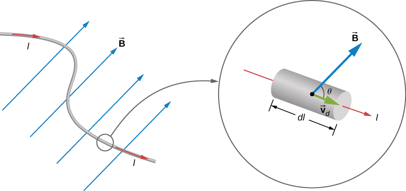
Magnetic force on a short current-carrying wire segment in a uniform magnetic field. The current runs along the wire, the field makes an angle θ with the segment, and the resulting force is perpendicular to both. The use of vector notation and the element dl goes slightly beyond OCR requirements but illustrates the general relationship F = B I L sinθ. Source.
The presence of the sinθ term highlights that the force depends on orientation. When the wire is aligned perpendicular to the magnetic field, the sine function equals one, giving the maximum possible force. If the wire lies parallel to the field, sinθ equals zero, meaning no force acts. This angular dependence reinforces that magnetic forces act only on components of motion (or current) that cut across magnetic field lines.
Direction of the Force
Although the quantitative expression gives the magnitude of the force, students must also identify its direction. While direction is covered more formally under Fleming’s left-hand rule in a separate subsubtopic, it is helpful here to emphasise that the force is always perpendicular to both the current and the magnetic field. This three-way perpendicular arrangement is characteristic of magnetic interactions and illustrates why such systems can produce rotational motion efficiently.
Understanding this geometry prepares students for applications such as electric motor design and helps reinforce the fundamental vector nature of magnetic forces.
Experimental Determination of Magnetic Flux Density
The OCR specification requires students to outline techniques for determining a uniform magnetic flux density using a current-carrying wire and a balance. These methods enable the practical evaluation of B, rather than treating it purely as a theoretical quantity.
In a typical school-level experiment, the conductor is placed in a uniform magnetic field created by high-quality permanent magnets or an electromagnet. The arrangement allows students to measure the force using a balance or scales. By adjusting and measuring variables carefully, they can obtain the value of B using the force equation.
In a typical setup, the magnet assembly is placed on a top-pan balance, with a straight wire or small coil running between the poles and connected to a variable d.c. supply.
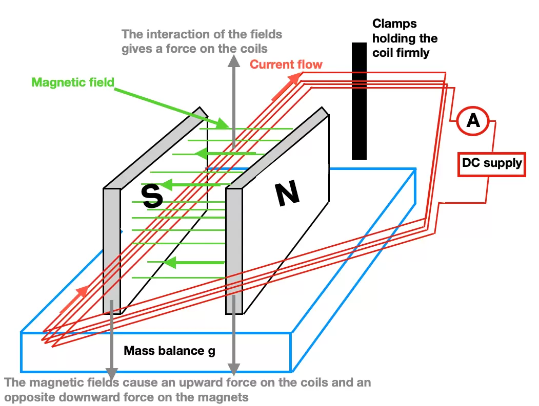
Experimental setup showing a magnet on a balance with a current-carrying wire between its poles. As current flows, the magnetic force alters the balance reading, allowing B to be calculated using F = B I L. The diagram includes a multi-turn coil rather than a single straight wire, but the operating principle matches the OCR-required technique. Source.
Because the magnetic force can act upward or downward depending on current direction, the balance reading shifts accordingly. This change provides a measurable quantity from which the force can be determined.
Normal mass balances read changes in weight rather than force directly, so the shift observed corresponds to the equivalent weight of the magnetic force. Converting this to newtons uses the standard relationship between mass and weight.
Procedure Outline
Students should be able to describe the essential procedural steps using clear, structured reasoning:
Adjust the experimental apparatus so that the wire lies fully within the region of uniform magnetic field.
Set the current to a chosen value and observe the change in balance reading.
Convert the balance reading change into a force acting on the wire.
Use the known values of I, L, and θ (normally 90° for maximum effect) to calculate B from the equation F = B I L sinθ.
Repeat the measurement with several current values to improve reliability and check proportionality between force and current.
Such experiments consolidate theoretical learning by reinforcing the direct connection between measurable quantities and the physical definition of magnetic flux density.
Applications and Significance
Understanding the force on a current-carrying wire equips students with essential knowledge used widely in physics and engineering. Devices such as electric motors, moving-coil meters, and magnetic sensors rely on this interaction. The ability to calculate the force precisely and determine magnetic flux density experimentally provides a strong foundation for later studies in electromagnetism and technological applications.
Practice Questions
Question 1 (2 marks)
A straight wire of length 0.12 m carries a current of 3.0 A perpendicular to a uniform magnetic field of flux density 0.40 T.
Calculate the magnitude of the magnetic force acting on the wire.
Question 1 (2 marks)
Using F = B I L:
• Substitution: F = 0.40 × 3.0 × 0.12 (1 mark)
• Correct final answer: 0.144 N (allow 0.14 N) (1 mark)
Question 2 (5 marks)
A student uses a top-pan balance to determine the magnetic flux density between the poles of a pair of magnets. A straight wire is placed horizontally between the poles so that it lies at right angles to the magnetic field. When a current flows through the wire, the reading on the balance decreases.
(a) Explain why the balance reading changes when current flows through the wire. (2 marks)
(b) The student records the change in balance reading for different currents. Describe how the student can use these measurements to calculate the magnetic flux density. Your answer should include the relevant equation and a clear outline of the method. (3 marks)
Question 2 (5 marks)
(a)
• The current in the wire experiences a magnetic force in the field. (1 mark)
• This force acts on the magnet system, causing an equal and opposite reaction force that changes the balance reading. (1 mark)
(b)
• The balance reading change is converted into a force by multiplying the mass change by g. (1 mark)
• Use of F = B I L (sin theta may be mentioned but theta = 90 degrees). (1 mark)
• Rearranging to B = F / (I L) and stating that repeated measurements with different currents are used to calculate and check consistency of B. (1 mark)
FAQ
The magnetic force arises from the interaction between moving charges in the wire and the magnetic field. Only the charges that are physically inside the field experience this interaction.
If the field is non-uniform or only occupies a limited space, the force acts solely on the wire segments that cut through magnetic field lines.
This is why experimental setups ensure the measured length of wire is fully within the uniform field: it guarantees that the force calculation using F = B I L applies accurately.
The magnetic force depends on current, not the physical size or material of the wire, provided the same current flows.
However, these factors can indirectly influence the force:
• A thicker wire may allow higher currents without overheating, increasing the force if current is raised.
• Resistivity of the material affects how easily current flows, influencing achievable current values.
• Mechanical stiffness can change how easily the wire physically moves under the force.
The force decreases because it depends on the sine of the angle between the wire and the field.
Small misalignments reduce the effective component of current cutting across field lines.
Large misalignments may introduce measurement errors, particularly when calculating B, because assuming sin 90 degrees = 1 would no longer be valid.
To minimise this, experimental setups often use alignment guides or fixed rails to ensure orientation remains as close to perpendicular as possible.
The direction of the magnetic force depends on the direction of the current relative to the magnetic field.
Reversing the current reverses the direction of the force.
If the force acts upward on the wire, it pushes downward on the magnet system, increasing the reading on the balance.
If the force acts downward on the wire, the opposite occurs and the balance reading decreases.
This equal and opposite reaction follows directly from Newton’s third law.
A uniform field ensures the magnetic flux density is constant along the length of wire used for measurement, making F proportional to L and allowing accurate use of F = B I L.
If the field varied significantly:
• Different wire segments would experience different forces.
• The measured force would be an average, not a true indication of the intended field strength.
• Calculated values of B would be unreliable or inconsistent across repeated trials.
Uniform fields, typically created by well-shaped permanent magnets or calibrated electromagnets, reduce these uncertainties.
