
OCR Specification focus:
‘Recognise field patterns for a long straight current-carrying wire, a flat coil, and a long solenoid.’
Magnetic field patterns allow us to understand how currents create structured magnetic regions. Recognising these patterns helps explain interactions in devices based on conductors, coils, and solenoids.
Understanding Magnetic Field Representation
When studying magnetic fields produced by conductors and coils, it is essential to interpret the shapes and directions of the fields that form around them. These patterns demonstrate how moving charges generate magnetic effects, and they reveal the geometry-dependent behaviour that underpins many electrical technologies.
Magnetic Field Lines
Magnetic fields are commonly represented using magnetic field lines, which provide a visual map of field direction and strength.
Magnetic field line: A continuous line that shows the direction of the magnetic field at each point, drawn from the North to the South pole of a magnet or following the direction a free north pole would move.
Magnetic field lines become denser where the field is stronger and never cross one another. This representation helps distinguish how the field behaves around different current-carrying shapes such as straight wires, flat coils, and solenoids.
Field Pattern for a Long Straight Current-Carrying Wire
A long straight wire carrying a steady current produces a characteristic circular magnetic field around it.
Key Features
The field forms concentric circles centred on the wire.
The direction of the field follows the right-hand grip rule, where the thumb points in the direction of conventional current and the fingers curl in the direction of the magnetic field lines.
The field strength decreases with distance from the wire, so lines are drawn further apart as the radius increases.
For an infinitely long wire, the field pattern is perfectly symmetrical; in real laboratory situations, the pattern closely matches this ideal except near the wire ends.
Understanding the Pattern
Because the wire is straight, the symmetry is cylindrical: rotating the diagram around the wire does not change the field map. Students should pay close attention to the direction of the circles, a key skill when interpreting magnetic interactions in devices such as circuit breakers, overhead power lines, or particle deflection systems.
Field Pattern for a Flat Circular Coil
A single turn of wire formed into a flat circular loop produces a more complex pattern that combines radial and axial magnetic components.
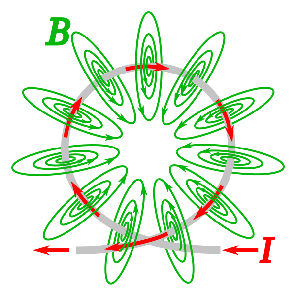
Magnetic field lines around a current-carrying circular loop are shown, with the strongest and most concentrated region at the coil’s centre. The diagram highlights how the axial field forms through the loop, supporting the description of field shape and direction. It includes no additional information beyond the field pattern and current direction. Source.
Key Features
At the centre of the coil, the field lines are approximately straight and perpendicular to the plane of the coil.
The field is strongest at the centre, where the lines are most concentrated.
Near the wire itself, field lines loop around the conductor in a manner similar to the pattern around a straight wire, but these loops merge to create a larger-scale pattern dominated by axial lines.
Outside the coil, the field spreads out and curves from one side of the coil to the other, forming a closed-loop structure.
Visual Interpretation
When interpreting diagrams of flat coil fields, the central region is the most significant. This is where uniformity is greatest, enabling flat coils to be used in magnetic sensors or in devices where a moderate, well-distributed field is required. The pattern can also be used to understand how multiple coils might reinforce or counteract one another when arranged in series or opposition.
Field Pattern for a Long Solenoid
A solenoid is a series of many circular loops wound closely together, typically forming a cylindrical shape.
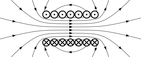
The diagram shows the magnetic field pattern produced by a solenoid, with strong, parallel field lines inside and weaker, curved lines outside. This visual representation supports the description of the solenoid’s nearly uniform internal magnetic field. It also depicts overall polarity, which provides context but does not exceed the syllabus requirements. Source.
Key Features
Inside a long solenoid, the field lines are parallel, evenly spaced, and directed along the axis of the cylinder. This demonstrates a strong and nearly uniform magnetic field, one of the defining characteristics of the solenoid.
Outside the solenoid, the field is much weaker and forms looping paths that connect the ends, resembling the pattern around a bar magnet.
The ends of the solenoid act like magnetic poles: one behaves as a North pole and the other as a South.
The right-hand grip rule applied to a solenoid (with fingers following the coil winding direction and thumb pointing along the axis) gives the direction of the internal magnetic field.
Reasons for the Uniform Interior Field
The near-uniform field arises from the cumulative effect of multiple overlapping coil fields. Each circular loop contributes a small axial component at the centre, and when many such contributions are stacked together, the field becomes straight and consistent across most of the interior. This makes solenoids extremely useful in electromagnets, electric bells, metrology instruments, and particle control systems.
Comparing the Three Field Patterns
Recognising the differences between these patterns is essential for OCR A-Level study:
Straight wire: circular symmetry, purely circumferential lines.
Flat coil: central region of straight axial lines with curved outer regions.
Solenoid: long, uniform axial field inside; weak external loops.
These distinctions form the basis for understanding how conductor shape influences magnetic behaviour and support the specification requirement to recognise the field patterns associated with these current-carrying structures.
Practice Questions
Question 1 (2 marks)
A student observes the magnetic field pattern around a long straight current-carrying wire using iron filings.
State the shape of the magnetic field lines and describe how their direction can be determined.
Question 1 (2 marks)
• Magnetic field lines form concentric circles around the wire. (1)
• Direction is given by the right-hand grip rule: thumb in direction of current, fingers show direction of field lines. (1)
Question 2 (5 marks)
A technician compares the magnetic field patterns produced by:
• a long straight current-carrying wire
• a flat circular coil
• a long solenoid
Describe the key features of each magnetic field pattern and explain why the solenoid produces a nearly uniform magnetic field inside it.
Question 2 (5 marks)
• Long straight wire: circular magnetic field lines centred on the wire. (1)
• Flat circular coil: field lines straight and concentrated through the centre; curved and looping around outside. (1)
• Solenoid: parallel, evenly spaced field lines inside showing a strong uniform magnetic field; weaker, looping field outside. (1)
• Explanation that the uniform field arises because the fields from individual loops add together to reinforce the axial component. (1)
• Mention that the close spacing and number of turns create overlapping contributions that straighten and strengthen the internal field. (1)
FAQ
Increasing the current increases the magnetic field strength, so the field lines become more densely packed. Decreasing the current weakens the field, spacing the lines further apart.
The circular shape of the field lines does not change, only their density.
The magnetic field contributions from all sections of the coil add together most effectively at the centre, where each segment produces a field in almost the same direction.
Towards the edges, the individual contributions no longer align perfectly, so the resulting magnetic field becomes weaker and more curved.
A solenoid produces the most uniform field when it is long compared with its diameter. Shorter solenoids show more variation in the field strength along their length.
Other factors include:
• the tightness and regularity of the winding
• whether an air core or magnetic core is used
• how close measurements are taken to the solenoid’s ends
Near the ends, the field lines begin to spread out and curve, as they transition from the internal axial field to the external looping field.
This reduces both the strength and the uniformity of the field compared with the central region, where contributions from all coil turns overlap more evenly.
Stacking several flat coils closely together begins to approximate a solenoid because their central fields combine to produce a stronger axial field.
However, unless the coils are numerous and tightly packed:
• the field will still be less uniform than that of a true long solenoid
• edge effects remain more pronounced
• the external field may be stronger and less controlled than in a solenoid
