
OCR Specification focus:
‘Construct clear free-body diagrams; resolve forces and apply equilibrium or resultant conditions.’
Free-body diagrams and the resolution of forces are essential tools for visualising and analysing how different forces act on an object, allowing accurate predictions of motion and equilibrium.
Understanding Free-Body Diagrams
A free-body diagram (FBD) is a simplified representation of an object showing all the external forces acting upon it. It isolates the body from its surroundings, enabling the study of force interactions without distraction from other system details.
Key Principles of Free-Body Diagrams
Only external forces acting on the object are shown — internal forces are ignored.
Each force is represented as an arrow. The length of the arrow indicates the magnitude, and the direction shows the line of action.
The arrow originates from the point of application, typically the centre of mass unless otherwise stated.
Each force must be labelled clearly with its type (e.g. weight, normal contact force, friction, tension, etc.).
Axes should be drawn when forces are to be resolved into components.
Common Forces Shown in Free-Body Diagrams
Weight (W) — the gravitational force acting vertically downwards.
Normal contact force (N) — the reaction force perpendicular to a surface.
Frictional force (F) — acts parallel to the surface opposing motion or impending motion.
Tension (T) — acts along a string, rope, or cable, pulling away from the object.
Air resistance or drag (D) — opposes motion through a fluid.
Upthrust (U) — the upward buoyant force acting on an object immersed in a fluid.
By showing these forces appropriately, the diagram becomes the foundation for any mechanical analysis of the system.
Free-body diagram: A diagram showing all the external forces acting on a single object, isolated from its surroundings.
An accurately drawn FBD allows identification of resultant forces and application of Newton’s laws of motion to predict motion or equilibrium.
Resolving Forces
When forces act at angles, it is often convenient to resolve them into perpendicular components — usually horizontal and vertical — to simplify calculations and understand their effects.
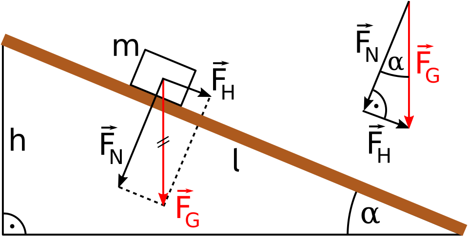
Inclined plane free-body diagram showing weight (W), normal contact force, friction, and the parallel and perpendicular components of weight. The axes are chosen along and perpendicular to the slope to simplify equilibrium/resultant conditions. Labels are minimal and syllabus-aligned. Source.
Resolving a force: The process of splitting a single force into two perpendicular components that together have the same effect as the original force.
Purpose of Force Resolution
Simplifies analysis by considering forces along independent directions.
Enables application of Newton’s second law (F = ma) separately in each direction.
Makes it easier to apply equilibrium conditions in static systems.
For example, a force acting at an angle θ to the horizontal can be resolved into:
A horizontal component (F cos θ)
A vertical component (F sin θ)
EQUATION
—-----------------------------------------------------------------
Force Resolution: Fx = F cos θ, Fy = F sin θ
F = Magnitude of the force (N)
θ = Angle between the force and horizontal (°)
Fx = Horizontal component of force (N)
Fy = Vertical component of force (N)
—-----------------------------------------------------------------
Once the components are identified, they can be combined with other forces in those directions to find resultant or balanced conditions.
Resultant and Equilibrium Conditions
Every object either remains at rest, moves with constant velocity, or accelerates due to a resultant force. Determining the net force acting on the object from the FBD is central to understanding its motion.
Resultant Force
The resultant force is the vector sum of all forces acting on the body. It determines both the magnitude and direction of acceleration.
EQUATION
—-----------------------------------------------------------------
Resultant Force (Fₑ) = √(ΣFx² + ΣFy²)
ΣFx = Sum of all horizontal components (N)
ΣFy = Sum of all vertical components (N)
—-----------------------------------------------------------------
The direction of the resultant can be found using trigonometry, typically tan⁻¹(ΣFy / ΣFx).
A non-zero resultant means the body will accelerate in the direction of that resultant. A zero resultant means the body is in equilibrium.
Equilibrium Conditions
When forces acting on an object are balanced, the object is said to be in equilibrium. For this state:
The sum of all horizontal forces = 0
The sum of all vertical forces = 0
Equilibrium: The condition in which all forces acting on a body balance so that the resultant force and resultant moment are both zero.
For OCR A-Level analysis, equilibrium refers mainly to translational equilibrium, where the object does not accelerate linearly in any direction.
Applying Equilibrium Conditions
To test for equilibrium or to solve unknown forces:
Draw an accurate free-body diagram with all known and unknown forces.
Choose perpendicular axes (horizontal and vertical, or along an incline and perpendicular to it).
Resolve angled forces into their components along each axis.
Apply equilibrium equations for each direction:
ΣFx = 0
ΣFy = 0
Solve for unknown forces such as tensions or normal reactions.
These steps are foundational in engineering, physics, and mechanics applications.
Using Vector Methods
For two-dimensional motion or complex force systems, vector addition can determine the resultant or verify equilibrium conditions graphically or analytically.
Vector Addition Principles
Forces can be represented as arrows drawn to scale, joined head-to-tail.
The resultant vector runs from the tail of the first to the head of the last force.
The triangle of forces or parallelogram method can show that if forces close a shape, they are in equilibrium.
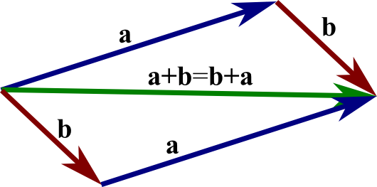
Parallelogram representation of vector addition, illustrating that the diagonal gives the resultant and that a + b = b + a. This directly underpins the graphical approach to finding a resultant or confirming equilibrium. The content is strictly within the syllabus focus on resolving forces and vector methods. Source.
EQUATION
—-----------------------------------------------------------------
Vector Sum: R = F₁ + F₂ + F₃ … (vector form)
R = Resultant force (N)
F₁, F₂, F₃ = Individual forces acting on the object (N)
—-----------------------------------------------------------------
If the vector sum equals zero, the object remains in equilibrium. Otherwise, the direction and magnitude of R indicate the resultant force and hence the direction of acceleration.
Triangle of forces: A graphical representation where three coplanar forces in equilibrium form a closed triangle when drawn to scale.
Accurate use of free-body diagrams and force resolution underpins all Newtonian mechanics, allowing consistent and logical application of physical laws to real-world systems.
Practice Questions
Question 1 (2 marks)
A 3.0 kg box rests on a horizontal surface. A horizontal force of 9.0 N acts on the box.
(a) Draw a labelled free-body diagram showing all the forces acting on the box.
Mark scheme:
1 mark: Correctly identifies and labels the weight (W) acting vertically downwards and the normal contact force (N) acting vertically upwards.
1 mark: Includes and labels the applied horizontal force (9.0 N) and frictional force (if present) acting in the opposite horizontal direction.
Question 2 (5 marks)
A block of mass 2.5 kg is placed on a smooth slope that makes an angle of 25° with the horizontal. The block is released from rest and slides down the slope.
(a) Draw a free-body diagram showing all the forces acting on the block.
(b) Resolve the weight of the block into components parallel and perpendicular to the slope.
(c) Hence, calculate the acceleration of the block down the slope. Take g = 9.81 m s⁻².
Mark scheme:
1 mark: Free-body diagram correctly shows weight (W) vertically downwards and normal reaction (N) perpendicular to the slope.
1 mark: Resolves weight into components correctly:
Parallel to slope: W sin θ
Perpendicular to slope: W cos θ
1 mark: Calculates the component of weight down the slope: 2.5 × 9.81 × sin 25° = 10.4 N (allow 10.3–10.5 N).
1 mark: States that resultant force = W sin θ (since no friction) and applies F = ma.
1 mark: Calculates acceleration: a = 10.4 / 2.5 = 4.16 m s⁻² (accept 4.1–4.2 m s⁻²).
FAQ
A free-body diagram (FBD) isolates a single object and shows only the external forces acting on it. Each object in a system must have its own FBD.
A force diagram for a system, however, can include multiple bodies and the forces they exert on each other. Internal forces appear here but are omitted from individual FBDs because they cancel when the system is viewed as a whole.
Choosing suitable axes simplifies the mathematical treatment of forces.
Align one axis with the direction of motion or the incline.
This makes one component of a key force (often weight) act entirely along one axis, reducing trigonometric complexity.
It allows equilibrium or resultant conditions to be applied cleanly: horizontal/vertical sums or sums along/perpendicular to a slope.
An inappropriate axis choice complicates calculations and can lead to sign errors when combining components.
Generally, no. A free-body diagram should show only the individual forces acting on the object, not their resultant.
However, once the individual forces are drawn, the resultant force vector can be added separately for illustration or explanation purposes—typically shown as a dotted or distinct arrow representing the net effect.
This distinction helps students visualise how multiple forces combine while maintaining clarity in identifying all external forces individually.
To verify completeness:
Identify all possible contact forces (normal, friction, tension, upthrust).
Add all relevant field forces (weight, electric, magnetic, etc.) depending on context.
Ensure forces are applied at correct points and have accurate directions.
Ask: “Could this object accelerate or move without one of these forces?” If yes, a force may be missing.
A common error is omitting reaction forces or misrepresenting the angle or orientation of forces.
When three coplanar forces act in equilibrium, they can be represented tip-to-tail as a closed triangle of forces.
Draw each force to scale, maintaining correct magnitude and direction.
If the triangle closes, the forces are balanced and the object is in equilibrium.
Unknown forces can be determined by constructing the triangle and measuring side lengths or angles.
This graphical approach offers a visual check for equilibrium without relying entirely on algebraic resolution.
