Charge flow, emf and circuit basics
Current is the rate of flow of charge: .
Direct current (dc) is a one-direction flow of charge carriers through a circuit.
Potential difference is the work done per unit charge in moving a positive charge between two points: .
Cells provide a source of emf: the energy supplied per unit charge by the source.
Know chemical cells and solar cells as sources of electrical energy.
Circuit diagrams show the arrangement of components using standard symbols.
In metal wires, electrons are the mobile charge carriers; conventional current is taken from positive to negative.
Ammeters measure current and are connected in series; voltmeters measure potential difference and are connected in parallel.
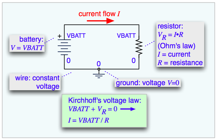
This diagram shows a simple dc circuit with a cell and a resistor, ideal for identifying current direction and potential difference across a component. It also helps connect the circuit symbols to the quantities used in Ohm’s law. This is useful for quick exam recall of the meaning of , , and a closed circuit. Source
Conductors, insulators and resistance
Conductors have mobile charge carriers, so charge can move through them easily.
Insulators have very limited charge carrier mobility, so current does not flow easily.
Resistance is the opposition to current in a material or component.
Electrical resistance is defined by .
Resistance arises from collisions of charge carriers with the lattice/ions/atoms of the material.
More collisions mean greater resistance and greater energy transfer to thermal energy.
For a wire, larger length gives larger resistance, while larger cross-sectional area gives smaller resistance.
Resistivity is a material property: .
A low resistivity material is a better conductor.
Ohm’s law and – behaviour
Ohm’s law: for an ohmic conductor at constant temperature, current is directly proportional to potential difference.
Therefore an ohmic conductor has constant resistance and a straight-line – graph through the origin.
A metal conductor at constant temperature is treated as an ohmic device.
Non-ohmic devices do not have constant resistance, so their – graph is curved.
For a resistor that heats up, rising temperature can increase resistance and make the graph non-linear.
The heating effect means electrical energy is transferred to thermal energy in the resistor.
In exams, always check whether the device is ohmic before assuming is constant.

This graph shows the linear current–voltage relationship of an ohmic conductor. A straight line through the origin means the resistance is constant. It is the key graph to recognize when applying Ohm’s law in IB questions. Source

This graph shows non-ohmic behaviour, where resistance changes as current and voltage change. The curved shape is typical of components whose temperature or internal properties vary during operation. Use it to compare directly with the straight-line ohmic graph. Source
.svg)
Power and heating in resistors
Electrical power is the rate of energy transfer in a circuit component.
For a resistor: .
Power dissipated by a resistor is usually transferred as thermal energy.
Use when both current and voltage are known.
Use when current and resistance are known.
Use when voltage and resistance are known.
Be careful to choose the equation that matches the values given most directly.
Series and parallel resistor combinations
In a series circuit, the current is the same through every component.
In series:
In series:
Adding resistors in series increases total resistance.
In a parallel circuit, the potential difference is the same across each branch.
In parallel:
In parallel:
Adding resistors in parallel decreases total resistance below the smallest branch resistance.
A common exam error is mixing up the current rule and voltage rule for series vs parallel.

This diagram directly compares series and parallel resistor arrangements. It helps you see that current is common in series while voltage is common in parallel. It is ideal for memorizing the circuit rules and equivalent resistance equations together. Source
Cells, emf and internal resistance
Real cells have emf and internal resistance .
The full circuit relation is .
This means some energy per unit charge is lost inside the cell because of its internal resistance.
The terminal potential difference across the external circuit is smaller than the emf when current flows.
If current increases, the lost volts inside the cell increase, so the terminal p.d. decreases.
A cell with smaller internal resistance is generally better at delivering current efficiently.
Be ready to compare advantages and disadvantages of different sources of electrical energy, especially chemical cells and solar cells.
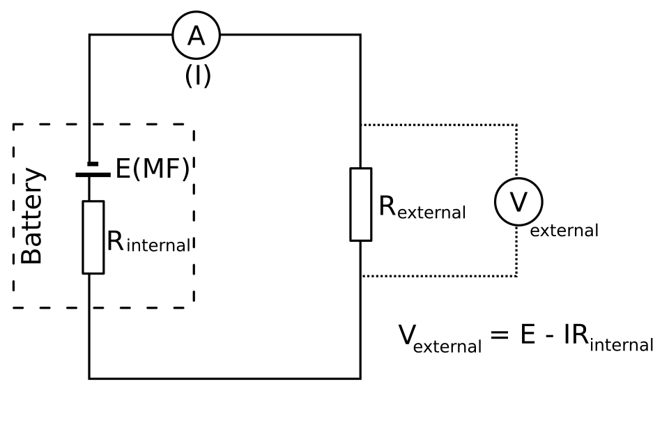
This circuit makes the idea of internal resistance visible by modelling the cell as an ideal source plus a resistor in series. It helps explain why the terminal potential difference is less than the emf when current flows. This is the clearest visual for lost volts inside a real cell. Source
Variable resistors and common exam contexts
Variable resistors change the resistance in a circuit.
Required examples are thermistors, light-dependent resistors (LDRs) and potentiometers.
A thermistor changes resistance with temperature.
An LDR changes resistance with light intensity.
A potentiometer provides an adjustable resistance and can be used to vary current or p.d. in a circuit.
In data questions, identify whether changing the environment changes the resistance, then predict the effect on current, voltage, or power.
Checklist: can you do this?
Define current, potential difference, resistance, resistivity, emf, and internal resistance precisely.
Apply Ohm’s law and the power equations to calculate missing circuit quantities with correct units.
Analyse series and parallel circuits, including finding equivalent resistance, branch currents and voltages.
Interpret – graphs to distinguish ohmic and non-ohmic behaviour.
Solve problems involving a cell with internal resistance using .