
OCR Specification focus:
‘Use appropriate digital instruments, including multimeters, for measurements such as time, current, voltage, resistance, and mass; use stopwatches or light gates for timing.’
Digital instruments are vital in modern physics experiments, providing precision, repeatability, and efficiency in collecting data across a range of measurements, from timing to electrical quantities.
Understanding Digital Instruments
Digital instruments convert analogue physical quantities into digital values for display and analysis. Their internal operation relies on analogue-to-digital conversion (ADC), allowing readings to be shown as discrete numbers rather than continuous scales. This minimises parallax error, a common issue in analogue readings, and increases accuracy when comparing or recording measurements.
Common Digital Instruments
Digital Multimeter (DMM) – measures voltage, current, resistance, and sometimes capacitance or temperature.
Digital Balance – measures mass electronically using strain gauges or electromagnetic force compensation.
Digital Thermometer – provides accurate temperature readings with fast response times.
Data Logger – automatically records readings over time, often integrating sensors and software tools.
Digital Stopwatch or Light Gate System – measures time intervals with high precision, especially in motion and dynamics investigations.
Digital instruments are standard in A-Level practicals because they enhance reproducibility and reduce uncertainty compared to analogue devices.
Principles of Measurement Using Digital Instruments
Voltage, Current, and Resistance
A digital multimeter can operate in several modes. In voltmeter mode, it measures potential difference across a component by comparing the input voltage to an internal reference. In ammeter mode, it measures current by detecting the voltage drop across a precision resistor. In ohmmeter mode, it measures resistance using Ohm’s Law.
EQUATION
—-----------------------------------------------------------------
Ohm’s Law (V, I, R) = V = I × R
V = potential difference (volts, V)
I = current (amperes, A)
R = resistance (ohms, Ω)
—-----------------------------------------------------------------
When measuring these quantities, circuit configuration is crucial:
Voltmeter: connected in parallel with the component.
Ammeter: connected in series.
Resistance: measured when the component is isolated from power to avoid current interference.
Modern digital multimeters use high internal resistance when measuring voltage to minimise current draw, improving accuracy. When measuring current, the burden voltage—the small voltage drop across the meter—should be considered as a potential source of systematic error.
Timing Measurements
Accurate timing underpins many experiments, from oscillations to motion analysis.
Digital stopwatches measure intervals to 0.01 s or better, depending on the model.
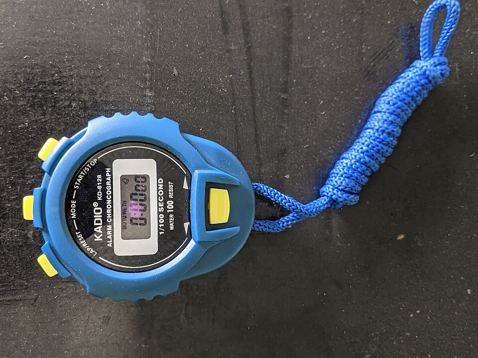
A digital stopwatch with 0.01 s resolution used for measuring time intervals in school laboratory investigations. While convenient, readings are limited by human reaction time when starting/stopping manually. The image contains no extraneous technical content beyond what is needed for A-Level use. Source.
However, human reaction time introduces uncertainty when starting or stopping manually.
Light gates overcome this by detecting the interruption of a light beam by an object. They are connected to data loggers or timing units that automatically record the time when the beam is broken. This eliminates reaction error and improves precision, particularly in free-fall, velocity, and acceleration experiments.
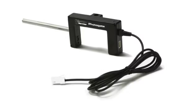
A photogate with integral infrared emitter–detector pair used to time objects passing through the gate. The device supports gate, pulse, and motion timing modes and can be daisy-chained for multi-gate setups; some models support a laser-gate mode. Minor extra product details (e.g., accessories) appear on the page but are not required by the syllabus. Source.
Light Gate: A sensor that measures the time an object interrupts a light beam, used for determining speed and time intervals accurately.
Some advanced systems use multiple light gates or ultrasonic sensors to measure motion parameters automatically, allowing calculation of instantaneous speed or acceleration.
Calibration and Accuracy
Digital instruments must be calibrated regularly to ensure reliability. Calibration involves comparing the instrument’s readings with those from a known standard under the same conditions.
For example:
A digital voltmeter can be calibrated using a precision voltage reference.
A balance can be calibrated using standard masses.
Calibration reduces systematic errors, while repeat measurements and averaging help reduce random errors.
Calibration: The process of adjusting an instrument’s readings by comparison with a known standard to ensure accurate measurement.
Accuracy in digital devices is expressed using specifications like ±(% reading + digits). For instance, a DMM rated at ±(0.5% + 2 digits) reading 10.00 V could have an uncertainty of ±0.07 V.
Data Logging and Digital Integration
Modern physics laboratories increasingly use ICT tools to automate measurements. Digital instruments often interface with computers or microcontrollers via USB, Bluetooth, or wireless connections.
Data loggers can record multiple variables simultaneously, such as voltage, current, and temperature, at predefined sampling intervals. These readings are processed using software tools for graphing and statistical analysis. This supports compliance with OCR requirements for scientific presentation of data and encourages good practice in data management.
When using software or sensors:
Check that the sampling rate matches the dynamics of the experiment (e.g., at least ten times faster than the expected change rate).
Ensure that the zero reading is correct before data collection.
Save and label datasets with clear units and metadata.
Advantages and Limitations
Advantages
High precision and resolution for electrical and timing measurements.
Reduced human error in reading scales or timing events.
Automated data storage, supporting easier analysis and replication.
Wide measurement range and versatility across multiple quantities.
Limitations
Dependence on power supply or batteries.
May be affected by electromagnetic interference or noise.
Some instruments require regular calibration to maintain accuracy.
May have sampling delays or limits in response time for fast-changing quantities.
Best Practice in Using Digital Instruments
To meet OCR practical expectations:
Always zero or tare the instrument before use.
Note the instrument range and resolution in data tables.
Record all units and uncertainties with each measurement.
For timing, use automatic systems (light gates or sensors) whenever possible.
If manual timing is required, repeat the measurement and average results to reduce human error.
When recording voltage or current, allow readings to stabilise before noting the value.
Keep the environment stable (temperature, vibration, electromagnetic conditions) to minimise drift.
By mastering digital measurement and timing techniques, students demonstrate the ability to apply precision, safety, and critical analysis—key practical competencies in OCR A-Level Physics.
Practice Questions
Question 1 (2 marks)
A student uses a digital stopwatch to time ten oscillations of a pendulum. The stopwatch has a resolution of 0.01 s.
(a) State one advantage of using a digital stopwatch rather than an analogue stopwatch.
(b) State one limitation of using a digital stopwatch in timing oscillations.
Mark Scheme
(a) One mark for any of the following:
Higher precision/resolution in time measurement (0.01 s).
Easier to read; no parallax error.
Digital display reduces reading uncertainty.
(b) One mark for any of the following:
Human reaction time introduces uncertainty when starting/stopping manually.
May not capture very short intervals accurately if started/stopped by hand.
Relies on battery power or electronic reliability.
Question 2 (5 marks)
In an experiment, a student measures the time taken for a trolley to pass between two light gates connected to a data logger. Each light gate is placed 0.80 m apart. The data logger records the time between interruptions of the light beams as 1.60 s.
(a) Explain why light gates are preferred to manual timing with a stopwatch. (2 marks)
(b) Calculate the average speed of the trolley. Show your working. (1 mark)
(c) Describe one possible source of systematic error in the measurement and explain how it could be reduced. (2 marks)
Mark Scheme
(a) Two marks for any two of:
Removes human reaction time errors, increasing precision.
Automatic timing gives consistent start and stop points.
Data is recorded electronically, reducing reading/parallax error.
(b) One mark for correct calculation:
Average speed = distance / time = 0.80 / 1.60 = 0.50 m s⁻¹
(c) Two marks for:
Identifying a valid systematic error (1 mark), e.g.:
Misalignment of light gates with trolley path.
Incorrect measurement of gate separation.
Delayed triggering if the beam is not fully broken.
Explaining how to reduce it (1 mark), e.g.:
Ensure gates are level and perpendicular to motion.
Use a fixed, accurately measured gate spacing.
Check triggering using a test pass to confirm sensor response.
FAQ
Resolution is the smallest change in a quantity that an instrument can detect — for example, a digital stopwatch with a 0.01 s display cannot show smaller intervals.
Precision refers to the repeatability or consistency of readings. An instrument may have high resolution but still give imprecise results if it produces varying values under the same conditions.
High-quality digital instruments aim for both high resolution and high precision through stable electronics and well-calibrated sensors.
Fluctuating readings can occur due to:
Electrical noise or interference from mains power or nearby devices.
Unstable connections or loose probes.
Automatic range switching in the multimeter.
To minimise fluctuations:
Use shielded leads or twisted pairs.
Select a fixed measurement range instead of auto-ranging.
Ensure the circuit and components are stable and connections are secure.
A light gate consists of a light source (often infrared) and a detector aligned to form a beam. When an object passes through, it interrupts the beam, triggering a signal.
This interruption is timed electronically, and the interval between two such signals is used to calculate quantities like speed or acceleration.
Multiple gates or beam pairs can be combined to measure velocity changes or to automate more complex motion analysis.
Digital instruments rely on internal reference voltages and software-based scaling. Over time, these can drift due to component ageing, temperature changes, or power fluctuations.
Regular calibration ensures that the digital readings correspond to the true physical values.
Analogue instruments often show gradual mechanical drift, whereas digital errors can appear as sudden step changes, making calibration even more essential for reliable accuracy.
Yes. Environmental conditions can influence both sensors and electronics in subtle ways:
Temperature: Affects resistance in circuits and timing oscillator stability.
Humidity: Can cause condensation on sensors or contacts.
Electromagnetic interference: Distorts signals from digital devices or data loggers.
Mitigation strategies include shielding cables, stabilising ambient conditions, and using grounded benches in precision experiments.
