
OCR Specification focus:
‘Construct circuits from diagrams and design, build, and check DC circuits with a range of components, including those where polarity is important.’
Designing and constructing DC (direct current) circuits is a fundamental practical skill in A-Level Physics, requiring accuracy, logical reasoning, and safe handling of electrical components and equipment.
Understanding DC Circuits
A DC circuit is one in which electric current flows steadily in one direction from a power supply through conductive paths and components before returning to the source. Unlike alternating current (AC), the voltage in a DC circuit remains constant over time. This makes DC circuits ideal for learning about circuit behaviour, resistance, and power.
Direct Current (DC): Electric current that flows continuously in one direction, maintained by a constant potential difference.
In practical physics, students must be able to interpret circuit diagrams, assemble circuits correctly, and verify that they operate as intended. This skill underpins experimental design and supports accurate measurement and data collection.
Circuit Design Principles
Designing a DC circuit begins with understanding the purpose of the experiment. A well-designed circuit is efficient, minimises error, and achieves clear, measurable results. Key design considerations include:
Purpose: Identify what is being measured or investigated (e.g., resistance, potential difference, current).
Components: Select suitable resistors, power sources, switches, meters, and connecting leads.
Polarity: Ensure correct connection of components like diodes, electrolytic capacitors, and power supplies, as incorrect polarity can damage equipment or cause inaccurate readings.
Safety: Use appropriate voltage levels and avoid overheating wires or components.
A clear, labelled circuit diagram should always be drawn before construction. It acts as a reference to identify connection errors and predict expected results.
Circuit Construction Techniques
When constructing a DC circuit from a diagram, systematic methods ensure accuracy and safety. The process typically involves:
Planning: Review the diagram and identify all components required.
Assembly: Build the circuit step by step, connecting components with secure, low-resistance connections.
Verification: Use a multimeter or continuity tester to check connections before applying power.
Testing: Power the circuit briefly to confirm function, observing meter readings and component operation.
Adjustment: Modify the layout or components as needed for accuracy or efficiency.
Always disconnect power sources before altering a circuit to prevent electric shock or equipment damage.
Common Circuit Components
Understanding each component’s purpose and symbol is essential when constructing circuits:
Power Supply: Provides the driving voltage or current. A DC power pack or battery is commonly used.
Resistor: Limits current flow and sets voltage drops in the circuit.
Variable Resistor (Rheostat): Allows controlled adjustment of resistance.
Capacitor: Stores electrical charge; polarity-sensitive if electrolytic.
Diode: Allows current to flow in one direction only; must be correctly oriented (anode to positive).
Ammeter: Measures current; connected in series with the circuit.
Voltmeter: Measures potential difference; connected in parallel across a component.
Switch: Opens or closes the circuit safely.
Connecting Wires: Provide low-resistance paths between components.
Incorrect use or connection of these elements can produce faulty readings or prevent the circuit from operating.
Measuring Current and Voltage
Accurate measurement of current and voltage is vital for data reliability. The correct connection of measuring instruments prevents damage and ensures valid results.
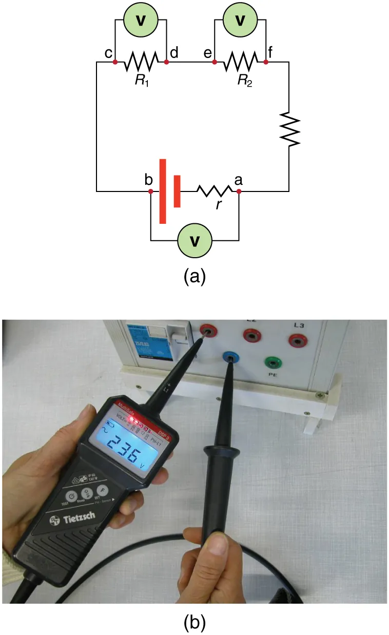
Schematic showing standard meter placement in DC circuits. The voltmeter (V) is connected in parallel across a component or source, whereas the ammeter (A) is placed in series with the branch being measured. This layout minimises measurement error and avoids meter overload. Source.
EQUATION
—-----------------------------------------------------------------
Ohm’s Law (R) = V / I
V = Potential difference (volts, V)
I = Current (amperes, A)
R = Resistance (ohms, Ω)
—-----------------------------------------------------------------
Ohm’s Law forms the basis for many DC circuit investigations, allowing relationships between voltage, current, and resistance to be determined experimentally.
Polarity and Circuit Checking
Polarity refers to the direction of current flow or the positive and negative terminals of a component. Devices such as LEDs, electrolytic capacitors, and power supplies have strict polarity requirements. Reversing connections may lead to malfunction or permanent damage.

Light-emitting diode (LED) symbol annotated to show A (anode, +) and K (cathode, −) per EN convention. Use this as a quick reference when orienting LEDs on breadboards or PCBs. Note: the symbol focuses on polarity and does not include extra device physics — ideal for construction tasks. Source.
When checking circuits:
Confirm that positive and negative terminals match the diagram.
Trace the circuit path to verify continuity.
Ensure no short circuits (unintended direct connections) exist.
Inspect for loose connections or frayed wires.
Verify instrument calibration before taking readings.
A circuit can be tested without powering sensitive components initially by using a low-voltage test or simulation software to model expected behaviour.
Breadboards and Soldering
DC circuits may be assembled on breadboards or using soldered joints, depending on permanence and accuracy required.
Breadboards are ideal for temporary circuits; they allow quick modification and reuse of components. Ensure wires are firmly inserted and correctly routed.
Soldered circuits offer reliable, permanent connections suitable for repeated measurements or demonstrations. Safe soldering practices must be observed—avoid inhaling fumes and keep soldering irons on heat-resistant surfaces.
Always verify circuit function after assembly before recording data.
Practical Skills and Safety
Effective circuit work requires discipline and precision. Students should demonstrate:
Accurate interpretation of diagrams before construction.
Logical troubleshooting if the circuit does not perform as expected.
Awareness of component ratings, ensuring voltage and current limits are not exceeded.
Consistent recording of observations in a lab notebook, including measured values and any adjustments made.
Safety is paramount. Wires should be arranged neatly to prevent tangling, and power should be disconnected before changing connections. Components such as resistors should not exceed their power rating, which can be calculated as:
EQUATION
—-----------------------------------------------------------------
Electrical Power (P) = I × V
P = Power (watts, W)
I = Current (amperes, A)
V = Potential difference (volts, V)
—-----------------------------------------------------------------
Monitoring component temperature and circuit stability ensures experimental reliability and protects against overheating.
Final Verification and Data Use
Before recording measurements, always perform a final verification:
Check all polarities and connections.
Confirm meters read zero when the circuit is inactive.
Note environmental factors that may affect results (temperature, contact resistance).
Record all values systematically with correct units and significant figures.
By mastering the design and construction of DC circuits, students gain essential practical and analytical skills central to experimental physics. These competencies enable accurate data collection, reinforce theoretical understanding, and reflect professional laboratory practice.
Practice Questions
Question 1 (2 marks)
A student connects a voltmeter in series with a resistor instead of in parallel when measuring potential difference.
(a) State one effect this incorrect connection will have on the circuit readings.
(b) Explain why this effect occurs.
Mark Scheme:
(a) (1 mark) – The voltmeter will give an incorrect or very small reading / the circuit current will decrease.
(b) (1 mark) – Because voltmeters have a very high resistance, connecting it in series restricts current flow through the circuit.
Question 2 (5 marks)
A student is asked to design and construct a DC circuit to determine the resistance of an unknown resistor.
Describe the steps they should follow to design, build, and check the circuit to ensure accurate and safe results.
Mark Scheme:
(1 mark) Draw a clear circuit diagram showing the resistor, power supply, ammeter in series, and voltmeter in parallel.
(1 mark) Check polarity of the power supply and connect meters with correct orientation (ammeter in series, voltmeter in parallel).
(1 mark) Use appropriate voltage levels to avoid overheating the resistor; switch off between readings.
(1 mark) Record current and voltage readings accurately for at least three different voltages to determine resistance using V = IR.
(1 mark) Verify the circuit by checking connections with a multimeter or continuity tester before applying power.
FAQ
Start by visually inspecting all connections for loose wires or incorrect placements. Then, use a multimeter to test continuity across each component and connection, confirming that current can flow.
If the circuit remains inactive:
Check the polarity of the power source and any diodes or LEDs.
Replace suspected faulty components one at a time.
Verify the power supply output with a voltmeter before reconnecting.
Working systematically prevents damage and ensures an efficient troubleshooting process.
Excessive current can damage components, particularly resistors, LEDs, and transistors. Limiting current also prevents overheating of wires or contacts, which could alter resistance values and distort results.
You can reduce risk by:
Using a low supply voltage during initial testing.
Adding a series resistor to restrict current flow.
Switching off the supply between readings.
Controlled testing safeguards both equipment and measurement accuracy.
Contact resistance arises from imperfect joints at connections, such as loose clips, corroded terminals, or poorly inserted leads. It introduces small extra resistances that cause voltage drops, leading to lower measured currents than expected.
To minimise this:
Clean terminals before assembly.
Use secure, tight connections.
Keep wire lengths short and consistent.
These steps improve data reliability, particularly in precision resistance or current measurements.
Soldering involves heat and fumes, so it must be carried out responsibly. Key precautions include:
Working on a heat-resistant surface and keeping flammable materials clear.
Using ventilation or fume extraction to avoid inhaling flux vapours.
Handling the soldering iron by the insulated grip only.
Wearing eye protection to prevent splatter injuries.
Always unplug the iron when not in use and allow joints to cool before inspection.
LEDs are current-sensitive and can be destroyed by even small voltage increases. A series resistor limits the current through the LED, ensuring it operates within its safe range.
The resistor value is chosen using Ohm’s Law:
Determine the supply voltage.
Subtract the LED’s forward voltage (typically 1.8–3.3 V).
Divide by the desired current (around 10–20 mA).
This ensures brightness control and prevents thermal runaway or permanent damage to the LED.
