
OCR Specification focus:
‘Increase accuracy using methods such as timing multiple oscillations or using fiducial markers; use calipers and micrometers, including digital or vernier scales.’
Improving Accuracy and Measuring Small Distances
Accurate measurements are essential for reliable experimental results. In A-Level Physics, improving accuracy involves refining techniques, minimising uncertainty, and using precision instruments to measure small distances effectively.
Understanding Accuracy and Precision
Accuracy refers to how close a measurement is to the true or accepted value, while precision describes how consistently repeated measurements agree with each other. High precision does not necessarily mean high accuracy, as systematic errors can still cause consistent but incorrect readings.
Systematic Error: A consistent bias in measurement due to faulty equipment, calibration errors, or experimental design flaws.
Random errors, on the other hand, arise from unpredictable fluctuations such as human reaction time or environmental variations. Both must be managed to ensure reliable data.
Strategies for Improving Accuracy
Repetition and Averaging
Repeating measurements and calculating a mean value reduces the influence of random errors. Multiple trials ensure that outliers do not disproportionately affect results.
Take several readings of the same quantity under identical conditions.
Discard anomalous results only when justified.
Use statistical tools such as mean and standard deviation to describe variability.
Timing Multiple Oscillations
For time-based experiments, such as pendulum or oscillating spring investigations, timing multiple oscillations reduces human reaction time error. Measuring one complete oscillation may be unreliable due to start/stop delays.
EQUATION
—-----------------------------------------------------------------
Period (T) = Total time (t) ÷ Number of oscillations (n)
T = Time for one complete oscillation (s)
t = Total measured time (s)
n = Number of oscillations (no unit)
—-----------------------------------------------------------------
By timing ten or more oscillations, the relative uncertainty from reaction time becomes much smaller, improving the accuracy of the calculated period.
Fiducial Markers
Fiducial markers are reference points placed on an oscillating object or near a measurement scale to provide a consistent visual cue. This reduces judgement errors when identifying the start or end of motion.
Attach a small, contrasting marker to the midpoint of the motion path.
Align the marker with a fixed background reference to maintain consistency.
Use video capture to freeze frames and measure timing or displacement accurately.
Measuring Small Distances Accurately
Accurate small-distance measurements are crucial in laboratory work, particularly in mechanics and materials experiments.
Vernier Calipers
Vernier calipers are used to measure lengths, diameters, or depths to a resolution typically of 0.01 mm. They consist of a main scale and a vernier scale, which provides fine measurement between main scale divisions.
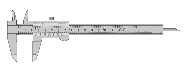
Labelled drawing of a 150 mm vernier caliper showing the main scale, vernier scale (1/50, 0.02 mm), jaws, and depth rod. Use this to visualise how the vernier reading adds precision between main scale divisions. The diagram also helps you locate components relevant to zero-error checks. Source.
Vernier Scale: A secondary scale that allows readings between main scale divisions for higher precision measurements.
To use vernier calipers effectively:
Ensure the jaws are clean and parallel before taking readings.
Close the caliper on the object gently to avoid compression.
Record both main scale and vernier scale readings, then combine them to obtain the final measurement.
Always check for zero error—when the caliper reads non-zero while closed—and correct the final measurement accordingly.
EQUATION
—-----------------------------------------------------------------
Measured Value = Main scale reading + Vernier scale reading – Zero error
Zero error = Reading when jaws are closed (mm)
—-----------------------------------------------------------------
Zero error correction ensures that systematic bias from calibration offsets is eliminated.
Micrometers
Micrometers, also known as screw gauges, measure even smaller distances, often to a precision of 0.001 mm. They operate using a finely threaded screw mechanism that translates rotational motion into precise linear displacement.
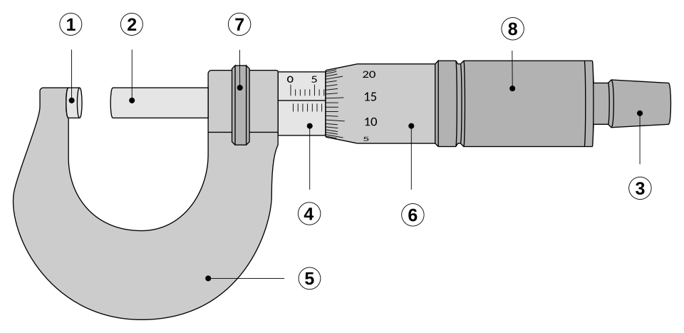
Illustration of an outside micrometer with anvil, spindle, sleeve scale, thimble scale, and ratchet indicated. The graphic shows a typical reading (≈7.145 mm) and demonstrates how the sleeve and thimble readings combine for high-resolution measurements. This directly supports correct reading and least-count awareness. Source.
To use a micrometer correctly:
Ensure the spindle and anvil are clean and free from dust.
Close the jaws gently using the ratchet stop to apply consistent pressure.
Read the measurement by combining the sleeve and thimble scales.
Apply zero correction if a discrepancy is present when fully closed.
Least Count: The smallest change in measurement detectable by an instrument, determined by the scale divisions and mechanical design.
The least count of a micrometer is typically 0.01 mm or 0.001 mm, depending on its construction. The smaller the least count, the greater the measurement precision.
Reducing Uncertainty in Small Measurements
Calibration and Instrument Maintenance
Calibration aligns the measurement scale of an instrument with a known standard. Regular calibration prevents cumulative systematic errors and ensures consistent accuracy across different measurements.
Compare the instrument with a certified reference gauge.
Adjust or note any offset errors.
Maintain tools by avoiding impact or temperature extremes that can alter dimensions.
Minimising Parallax Error
Parallax error occurs when the observer’s eye is not aligned perpendicularly with the measurement scale. To minimise it:
Position the eye directly above the scale mark.
Use mirrored scales where available to ensure alignment.
Employ digital displays to eliminate visual alignment errors entirely.
Environmental and Procedural Controls
Environmental factors such as temperature and humidity can influence measurements. For example, metal expansion due to heat can change length readings. Control these factors by:
Conducting experiments in stable laboratory conditions.
Allowing instruments to reach thermal equilibrium before use.
Avoiding draughts, vibrations, or unstable surfaces.
Digital Instruments for Enhanced Precision
Modern digital calipers and digital micrometers provide readings on electronic displays, reducing human reading error and eliminating the need for vernier interpretation. Many also include data logging features for direct computer recording.
Advantages of digital tools include:
Faster readings with minimal human error.
Automatic zeroing and unit conversion.
Capability to interface with data analysis software.
However, users must still verify calibration integrity and be aware of battery or electronic drift effects that could compromise accuracy.
Practical Application and Scientific Reporting
To ensure reproducibility and validity:
Record the instrument type, calibration details, and uncertainty values in lab reports.
Justify measurement choices—such as using micrometers instead of rulers—based on required precision.
Present data with appropriate significant figures and uncertainty notation, ensuring consistency between measured and derived quantities.
Through careful attention to measurement technique, error management, and tool selection, the accuracy of small distance measurements in experimental physics can be maximised, aligning with OCR’s emphasis on precision and reliability in practical work.
Practice Questions
Question 1 (2 marks)
A student measures the diameter of a thin wire using a vernier caliper. The main scale reads 5.00 mm, and the vernier scale shows 0.18 mm. The caliper has a zero error of –0.02 mm.
Calculate the corrected diameter of the wire. Show your working.
Mark scheme:
• Correctly adds main scale and vernier scale readings: 5.00 mm + 0.18 mm = 5.18 mm (1 mark)
• Applies zero error correction: 5.18 mm – (–0.02 mm) = 5.20 mm (1 mark)
Award both marks for correct final answer of 5.20 mm with appropriate working shown.
Question 2 (5 marks)
A student is using a micrometer to measure the thickness of a metal foil. The micrometer has a least count of 0.01 mm. The student records three readings: 0.24 mm, 0.25 mm, and 0.23 mm.
(a) Explain why taking multiple readings improves the accuracy of the result. (2 marks)
(b) Calculate the mean thickness and comment on the precision of the micrometer relative to the spread of results. (3 marks)
Mark scheme:
(a)
• Repetition allows identification of random errors and reduces their effect when calculating the mean. (1 mark)
• Multiple readings improve reliability by minimising the influence of any single anomalous result. (1 mark)
(b)
• Correct mean thickness: (0.24 + 0.25 + 0.23) ÷ 3 = 0.24 mm (1 mark)
• States that the results vary by ±0.01 mm, which is comparable to the micrometer’s least count, indicating good precision. (1 mark)
• Explains that small variation within instrument resolution suggests consistent measurement technique. (1 mark)
FAQ
The uncertainty is typically taken as half the instrument’s smallest scale division (its resolution).
For example:
Vernier caliper with a resolution of 0.02 mm → ±0.01 mm uncertainty.
Micrometer with a resolution of 0.01 mm → ±0.005 mm uncertainty.
When repeating measurements, calculate the range of readings and compare it to the instrument uncertainty. If the spread is larger than the resolution, the uncertainty is dominated by the variability in measurement rather than the tool itself.
Accuracy is how close a reading is to the true value.
Precision is how closely repeated measurements agree.
Resolution is the smallest detectable change in measurement an instrument can show.
A micrometer, for instance, has higher precision and resolution than a ruler but can still be inaccurate if it has a calibration or zero error.
Temperature changes cause metals to expand or contract, altering their dimensions and leading to systematic errors.
For accurate results:
Conduct measurements in a controlled environment, ideally around 20 °C.
Allow instruments and materials to reach thermal equilibrium before taking readings.
Avoid handling metal tools excessively, as body heat can cause slight expansion.
The ratchet stop ensures consistent measuring pressure between the spindle and the object. Without it, excessive tightening could compress the object or damage the instrument, leading to smaller or inconsistent readings.
Using the ratchet stop correctly allows for repeatable measurements by applying a uniform, gentle pressure every time the jaws close on the sample.
Digital instruments are ideal when:
Human reading errors (parallax or misalignment) are likely.
Rapid or repetitive measurements are required.
Data needs to be logged or analysed electronically.
However, analogue instruments like vernier calipers remain valuable for understanding scale reading principles and detecting subtle mechanical issues such as backlash or drift.
