
OCR Specification focus:
‘Outline gamma camera: collimator, scintillator, photomultiplier tubes, computer, display; explain image formation.’
A gamma camera detects gamma radiation from injected medical tracers, converting photon interactions into electrical signals to construct diagnostic images that reveal structure and function.
Gamma Camera Components
A gamma camera is a non-invasive nuclear medicine device designed to form images from gamma photons emitted inside the patient. It operates by capturing the spatial distribution of gamma radiation and converting it into a visible image representing physiological activity.
Collimator
The first major component encountered by incoming gamma photons is the collimator. It ensures only photons travelling along specific directions reach the detection crystal.
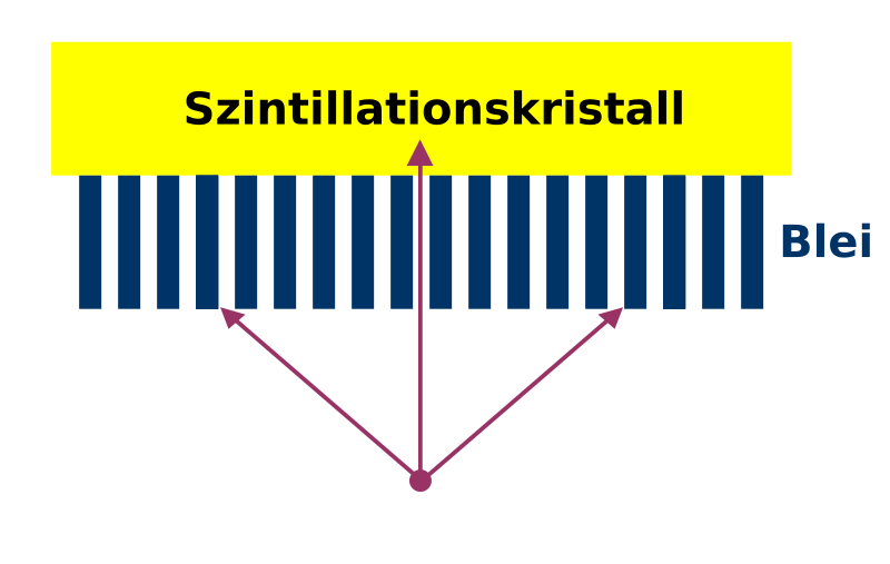
A schematic illustration of a parallel-hole collimator showing its many narrow channels that admit only near-parallel gamma photons. The design preserves spatial information for image formation. Extra detail included is the precise geometry of the hole arrangement, which supports understanding but exceeds syllabus requirements. Source.
Collimator: A lead or tungsten plate containing thousands of narrow channels that permit only near-parallel gamma photons to reach the scintillator.
A collimator is crucial because gamma photons cannot be focused with lenses. Instead, physical filtering is used to maintain spatial information. Modern cameras most commonly use parallel-hole collimators, though other designs such as pinhole or converging collimators appear in some specialised applications.
The collimator determines the trade-off between spatial resolution and photon count rate:
Narrow channels → higher resolution but fewer photons detected.
Wider channels → lower resolution but higher count rate.
This balance is important when imaging rapidly changing physiological processes.
Scintillator
Behind the collimator lies the scintillator, usually a large crystal of thallium-doped sodium iodide (NaI(Tl)). Its role is to convert incoming gamma photons into flashes of visible light known as scintillations.
Scintillator: A material that emits light photons when excited by ionising radiation such as gamma rays.
NaI(Tl) is chosen because it produces a strong, measurable light output when gamma photons interact within it. Interactions may involve the photoelectric effect or Compton scattering, producing energetic electrons that excite the crystal lattice. The resulting light flash occurs over nanoseconds, enabling rapid signal collection. The thickness of the scintillator is selected to optimise absorption probability while minimising image blurring caused by lateral photon spread.

A cross-sectional diagram of the gamma camera head showing the collimator, scintillation crystal, light guide, and photomultiplier tubes. It visualises the sequence of detection components and their spatial arrangement. Additional structural elements such as shielding appear but merely provide context. Source.
A gamma camera requires the scintillation process to be highly efficient in order to generate enough light photons for detection by the next component.
Photomultiplier Tubes (PMTs)
Situated behind the scintillator is an array of photomultiplier tubes, arranged in close-packed formation to sample the light flashes produced by gamma events.
Photomultiplier tube: A highly sensitive light detector that converts faint light flashes into amplified electrical signals using a photocathode and a cascade of dynodes.
When a scintillation occurs, its light spreads across several adjacent PMTs. Each PMT generates an electrical pulse with an amplitude proportional to the number of photons it receives. Because different PMTs detect varying proportions of the same light flash, the system can determine the event’s position using light-sharing techniques.
Between definition and equation blocks, it is important to appreciate that PMTs must amplify extremely weak signals, often representing only a few dozen light photons.
Position and Energy Computation
The camera’s position-sensing circuitry determines the X- and Y-coordinates of each gamma event. It analyses the relative pulse heights from multiple PMTs to pinpoint the location of the scintillation within the crystal. This approach is known as Anger logic, after Hal Anger, who developed the first practical gamma camera.
To improve image quality and eliminate scattered photons with lower energies, the system performs an energy discrimination step. Only events with energies within a predetermined “energy window” centred on the gamma emission energy of the tracer (commonly 140 keV for technetium-99m) are accepted.
Computer Processing
Signals from detected events are transmitted to the camera’s onboard computer, which performs several important functions:
Determines the precise position of each accepted event.
Applies corrections for individual PMT variation, uniformity, and non-linearity.
Stores event positions to gradually build up a two-dimensional intensity map.
Converts numerical matrices into an image suitable for clinical interpretation.
The image produced reflects radiopharmaceutical distribution within the patient, allowing clinicians to diagnose organ dysfunction or detect abnormal metabolic activity.
Image Formation in a Gamma Camera
From Gamma Photon to Image
The sequence of processes that convert an emitted gamma photon into a pixel within an image may be outlined as follows:
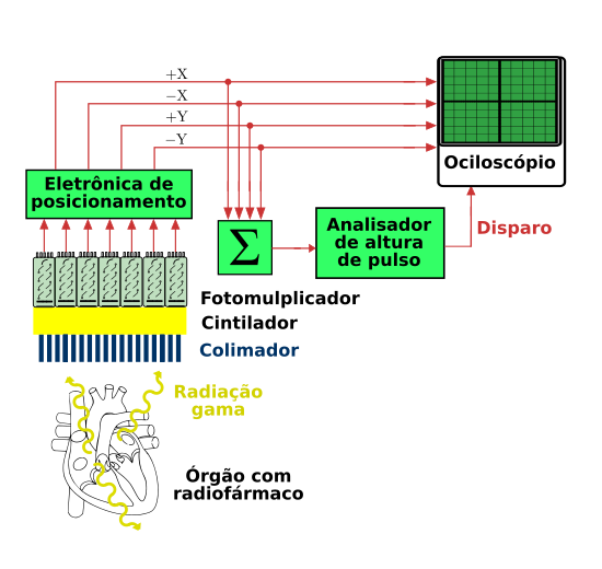
A block diagram of the gamma camera system showing the path from gamma detection through photomultiplier processing, electronic modules, the computer, and final display. It reinforces how individual gamma events become an image. Some electronic stages exceed syllabus detail but remain conceptually helpful. Source.
Emission: A radionuclide tracer injected into the patient emits gamma photons from specific tissues.
Direction selection: The collimator allows through only photons travelling in useful directions.
Scintillation: Each accepted photon interacts with the crystal and produces a faint flash of visible light.
Detection: Several PMTs sense the light flash and generate electrical signals.
Event localisation: The camera computer calculates the photon’s origin within the crystal plane.
Energy filtering: Events with energies outside the selected window are rejected to reduce noise.
Image accumulation: Each event adds to a position-intensity matrix that becomes the final displayed image.
Display System
The final component is the display, usually a digital monitor. The computer’s processed event matrix becomes a two-dimensional greyscale image in which:
Brighter regions indicate greater gamma activity, suggesting increased tracer uptake.
Darker regions indicate reduced activity, which may correspond to tissue damage or reduced function.
Because nuclear medicine imaging reflects physiological, rather than purely anatomical, information, gamma camera images can reveal disease processes at early stages before structural changes are visible on other imaging modalities.
Summary of Key Roles of Components
Although not a conclusion, it is useful to clarify the distinct contributions of each major component without summarising the entire text:
Collimator: Maintains spatial fidelity by selecting photon directions.
Scintillator: Converts gamma photons into detectable light flashes.
PMTs: Convert light to electrical signals and provide positional information.
Computer: Processes, filters and reconstructs the image.
Display: Presents the gamma activity map for diagnostic interpretation.
Practice Questions
Question 1 (2 marks)
State the function of the collimator in a gamma camera and explain why it is necessary for image formation.
Question 1 (2 marks)
1 mark: Correctly states that the collimator only allows gamma photons travelling in specific (near-parallel) directions to reach the detector.
1 mark: Explains that this is necessary to maintain spatial information or prevent photons from incorrect angles blurring the image.
Question 2 (5 marks)
Gamma cameras detect gamma photons emitted from medical tracers to produce images of internal physiological processes.
Describe how a gamma camera forms an image, including the roles of the scintillator, photomultiplier tubes, energy discrimination, and computer system.
Question 2 (5 marks)
Award marks for any five of the following points:
Scintillator absorbs gamma photons and produces flashes of visible light (scintillations).
Photomultiplier tubes detect these light flashes and convert them into electrical signals.
Relative signal strengths in multiple PMTs are used to determine the position of each gamma interaction.
Energy discrimination is applied to reject scattered photons that have lost energy.
The computer processes accepted events, corrects for variations, and constructs a two-dimensional intensity map to form the image.
FAQ
A narrower hole diameter improves spatial resolution because fewer off-axis photons pass through. However, it significantly reduces sensitivity, meaning longer imaging times or noisier images.
A thicker collimator enhances directional selectivity but also decreases the number of photons reaching the scintillator.
Clinically, collimators are chosen according to the tracer energy and the organ being imaged, balancing resolution and count rate for diagnostic usefulness.
Thallium acts as an activator, creating energy levels that allow efficient emission of visible light when the crystal is excited.
Using a different activator would change:
The wavelength of emitted light
The decay time of scintillation
The intrinsic light yield
Any mismatch with PMT sensitivity or timing electronics would reduce detector performance.
Light photons produced during scintillation scatter inside the crystal due to imperfections and internal reflection, making each flash spread across several PMTs.
This spreading is essential for Anger logic, which relies on differences in PMT signal amplitudes to determine event position.
However, excessive lateral light scatter reduces spatial resolution, so scintillator thickness and optical coupling are carefully optimised.
Computers correct for:
Non-uniform PMT gain
Variations in light collection efficiency across the crystal
Distortions caused by edge effects
Differences in energy response between PMTs
These corrections are produced from calibration scans using uniform radioactive flood sources to ensure image linearity and uniformity in clinical use.
Scattered photons lose energy during Compton interactions, so their detected energies fall below the tracer’s characteristic gamma-ray peak.
An energy window is positioned around this peak.
Photons inside the window are accepted
Photons below or above are rejected
The width of the window must be wide enough to account for detector energy resolution but narrow enough to exclude most scattered radiation, improving contrast without losing too many valid events.
