
OCR Specification focus:
‘Determine g experimentally using trapdoor–electromagnet timing or light gates with a suitable timer arrangement.’
Measuring the acceleration due to gravity, g, is a fundamental experiment in A-Level Physics. Accurate measurement demonstrates key principles of motion and experimental technique using controlled timing apparatus.
Determining the Acceleration due to Gravity
The acceleration due to free fall (g) is the rate at which an object accelerates towards the Earth when acted on only by gravity, with negligible air resistance. Near the Earth’s surface, this value is approximately 9.81 m s⁻². To measure g, students employ precise timing devices to capture the time taken for an object to fall through a known distance.
Key Principle
In ideal conditions, an object dropped from rest accelerates uniformly under gravity. This motion can be described using a constant acceleration equation.
EQUATION
—-----------------------------------------------------------------
Displacement (s) = ut + ½at²
u = Initial velocity (0 for free fall)
a = Acceleration (g, m s⁻²)
t = Time (s)
s = Displacement (m)
—-----------------------------------------------------------------
Rearranging for g, the experimenter can calculate:
g = 2s / t²
This equation forms the foundation of all methods used to determine g experimentally.
Experimental Approaches to Measuring g
Using a Trapdoor and Electromagnet
This is a classic, reliable method that combines mechanical release with electronic timing for minimal human error.
Apparatus
Electromagnet to hold a small steel ball above a trapdoor.
Low-voltage power supply with switch.
Trapdoor connected to an electrical circuit and timer.
Millisecond timer capable of measuring intervals accurately.
Rigid measuring apparatus (metre ruler or fixed scale).
Procedure
The steel ball is held in position by the electromagnet connected to a power supply.
When the current is switched off, the ball is released, simultaneously triggering the timer to start.
The ball falls freely under gravity.
Upon striking the trapdoor, the contact opens the circuit and stops the timer.
The distance between the electromagnet and the trapdoor is measured precisely.
The time recorded is used to calculate g = 2s / t².
This arrangement ensures both release and timing occur at the same instant, reducing reaction time errors and systematic delays.
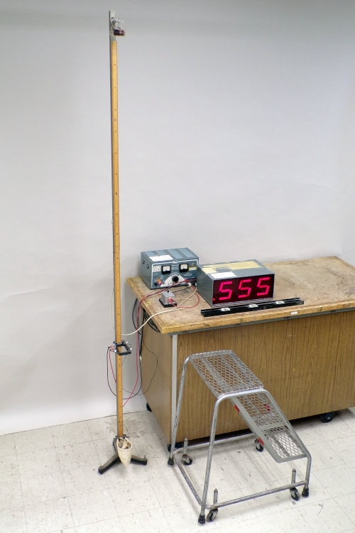
Electromagnet-release free-fall apparatus with a photogate and timer. The switch simultaneously de-energises the magnet and starts timing; passage through the light gate stops timing, enabling an accurate determination of g from height and fall time. The image includes a carpenter’s level for vertical alignment; this is helpful but not required by the syllabus. Source.
Considerations
Air resistance is negligible for small fall distances (typically <1 m).
Ensure the ball is released vertically to avoid horizontal motion.
Take multiple readings to minimise random errors and calculate an average value of g.
Using Light Gates
Light gates provide non-contact, highly precise timing and are ideal for modern laboratories using data loggers or digital timers.
Apparatus
Two light gates connected to an electronic timer or data logger.
A dense spherical object (e.g. a metal ball) with a card strip or opaque marker.
Stand or clamp to hold the upper light gate fixed above the lower one.
Measuring equipment to determine vertical distance accurately.
Procedure
Position the two light gates vertically apart by a measured distance s.
Release the ball from rest just above the first gate.
The first light gate detects when the ball passes and starts the timer.
The second light gate detects when the ball passes again and stops the timer.
Record the time of travel t between the two gates.
Calculate g = 2s / t², assuming the ball started from rest immediately before the first gate.
For the light-gate method, position a start gate near the release point and a stop gate lower down so the timer records the flight interval between the two beams.
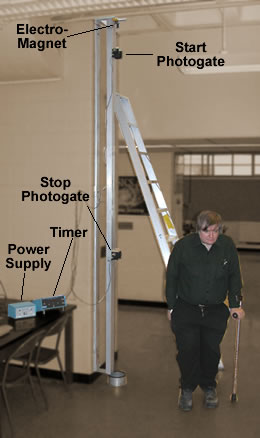
Annotated free-fall rig with an electromagnet at the top and two photogates used to start and stop timing as the ball passes. This arrangement eliminates delay uncertainties from the magnet itself and supports plotting distance vs t² or v² vs 2h to obtain g. The background ladder is incidental and not part of the required apparatus. Source.
Advantages
High precision because timing is automatic.
No parallax error as the gates detect light interruption electronically.
Can connect to data-logging software for instant data analysis and graphical output.
Improvements
Repeat with varying distances between gates to verify g’s constancy.
Account for initial velocity if the ball is released slightly above the first gate by adjusting equations using SUVAT principles.
Error Reduction and Accuracy
Minimising Random Errors
Take at least five measurements of t for each setup and compute the mean.
Ensure apparatus is stable and aligned vertically.
Record s using a fixed scale to millimetre precision.
Minimising Systematic Errors
Check that the timer triggers correctly when the current to the electromagnet is cut.
Confirm light gates are calibrated and aligned accurately.
Measure s from the point of release to the detection plane precisely.
Calculating Uncertainty
Uncertainty in g arises from both distance and time measurements. When combining these uncertainties, apply propagation of uncertainty principles, recognising that time errors often have a greater proportional effect due to s ∝ t².
Common Sources of Error
Delay between electromagnet deactivation and actual ball release.
Misalignment of trapdoor or uneven landing surface.
Air currents or drag, especially for light objects.
Incorrect distance measurement between light gates or release points.
Data Analysis and Validation
After obtaining multiple measurements:
Plot s against t² for varying drop heights.
The gradient of the graph gives ½g, providing an independent verification of results.
Compare experimental g with the accepted value (9.81 m s⁻²) to evaluate accuracy.
Experimental Enhancements
Employ data loggers to record precise timing intervals.
Use vacuum tubes to minimise air resistance in advanced setups.
Calibrate sensors before each run to remove offset errors.
Key Learning Outcomes
Understand that g is determined by measuring distance and time during free fall.
Recognise how trapdoor–electromagnet and light gate methods achieve precise, reliable timing.
Apply the constant acceleration equation s = ½gt² to link experimental measurements with theoretical prediction.
Evaluate experimental uncertainty, identifying practical improvements and the reliability of results.
These experiments exemplify the importance of controlled release, accurate measurement, and data validation in determining the acceleration due to gravity with high precision.
Practice Questions
Question 1 (2 marks)
A student releases a small steel ball from rest using an electromagnet and measures the time taken for it to fall 0.80 m before striking a trapdoor connected to a timer.
Explain how this arrangement helps to reduce timing errors when measuring the acceleration due to gravity.
Mark scheme:
1 mark: The timer starts automatically when the electromagnet releases the ball.
1 mark: The timer stops automatically when the ball hits the trapdoor, removing human reaction time error.
Question 2 (5 marks)
A student measures the acceleration due to gravity using two light gates positioned vertically 0.50 m apart. The ball is released from rest just above the first gate.
(a) State the equation used to calculate g from the distance s between the gates and the measured time t. (1 mark)
(b) Describe how the student should carry out the experiment to obtain an accurate value of g. (3 marks)
(c) Suggest one improvement to reduce systematic error. (1 mark)
Mark scheme:
(a)
1 mark: g = 2s / t²
(b)
1 mark: Release the ball from rest just above the first light gate to ensure negligible initial velocity.
1 mark: Measure the vertical distance between the light gates accurately using a metre rule.
1 mark: Repeat the measurement several times and calculate the mean value of t to reduce random error.
(c)
1 mark: Ensure the light gates are aligned vertically or calibrated correctly to avoid timing offsets.
FAQ
An electromagnet provides a consistent and precise release point for the falling object, eliminating variation caused by human reaction or mechanical friction.
When the current is switched off, the electromagnet releases the object and triggers the timer simultaneously. This ensures that both the start of motion and the start of timing occur at exactly the same instant, improving accuracy and reducing systematic error.
Air resistance opposes motion and causes the measured acceleration to be slightly less than the true value of g.
Its impact depends on:
The object’s shape and surface area (streamlined objects experience less drag).
The distance fallen (greater distance means higher speed and greater drag).
To minimise this effect, use small, dense objects like metal balls and limit the drop height to around one metre.
Light gates remove physical contact and mechanical delay, offering highly accurate and repeatable timing.
Advantages include:
Automatic triggering: The light beam interruption ensures immediate start and stop signals.
Reduced wear and tear: No moving parts, so less drift in timing precision.
Digital data collection: Enables direct connection to data loggers or computers for analysis.
These benefits make light gates especially effective for experiments requiring multiple measurements or graphical data analysis.
A single light gate measures instantaneous velocity at one point, but using two allows the calculation of acceleration over a known distance.
Two light gates provide:
Accurate timing between start and stop points.
Measurement of mean acceleration between the gates.
Reduction in timing uncertainty, as both events are automatically recorded.
This setup produces data suitable for verifying uniform acceleration and calculating g using the equation g = 2s / t².
Before running measurements, students should confirm:
The electromagnet releases the object cleanly without sticking.
Light gates are aligned vertically and detect the ball’s passage correctly.
The timer starts and stops reliably with each trigger.
The distance between release and detection points is measured precisely using a fixed scale.
Carrying out these checks ensures repeatable, accurate results and identifies faults before data collection begins.
