
Calculus serves as a pivotal tool in comprehending and modeling the dynamics of change across various contexts. This segment of study notes delves into the essence of calculus, highlighting its role in generalizing knowledge about motion and addressing diverse problems of change through the concept of limits. By engaging with these notes, students will gain insights into utilizing limits to conceptualize and solve problems involving dynamic change, a foundational aspect of calculus critical for further studies in this field.
Calculus serves as a pivotal tool in comprehending and modeling the dynamics of change across various contexts. This segment of study notes delves into the essence of calculus, highlighting its role in generalizing knowledge about motion and addressing diverse problems of change through the concept of limits. By engaging with these notes, students will gain insights into utilizing limits to conceptualize and solve problems involving dynamic change, a foundational aspect of calculus critical for further studies in this field.
Calculus serves as a pivotal tool in comprehending and modeling the dynamics of change across various contexts. This segment of study notes delves into the essence of calculus, highlighting its role in generalizing knowledge about motion and addressing diverse problems of change through the concept of limits. By engaging with these notes, students will gain insights into utilizing limits to conceptualize and solve problems involving dynamic change, a foundational aspect of calculus critical for further studies in this field.
Introduction to Limits
Limits are fundamental in calculus, allowing us to explore values that functions approach as the input reaches a certain point.
Definition of a Limit: Let be a function defined on an interval containing (except possibly at ) and let be a real number. The statement
means that for every there exists a such that if , then .
Intuitive Understanding: As approaches , the value of gets arbitrarily close to .
The Role of Limits in Understanding Dynamic Change
Limits provide the framework to quantify changes occurring in an instant, which are pivotal in understanding and modeling dynamic systems.
Example 1: Calculating Instantaneous Speed
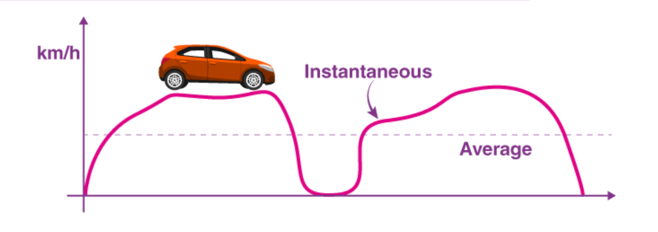
Image courtesy of BYJUS
Scenario: A car travels in a straight line and its position at time is given by , where is in meters and is in seconds. Find the car's instantaneous speed at seconds.
Solution:
Thus, the instantaneous speed of the car at seconds is meters per second.
Example 2: Understanding Change in Temperature
Scenario: The temperature in degrees Celsius at a specific location as a function of time in hours is given by . Calculate the rate of temperature change at hours.
Solution:
The rate of temperature change at hours is degrees Celsius per hour.
Application of Limits in Calculus
The application of limits extends beyond physical motion and temperature changes, encompassing economic models, biological growth patterns, and chemical reaction rates.
Example 3: Economic Model - Profit Maximization
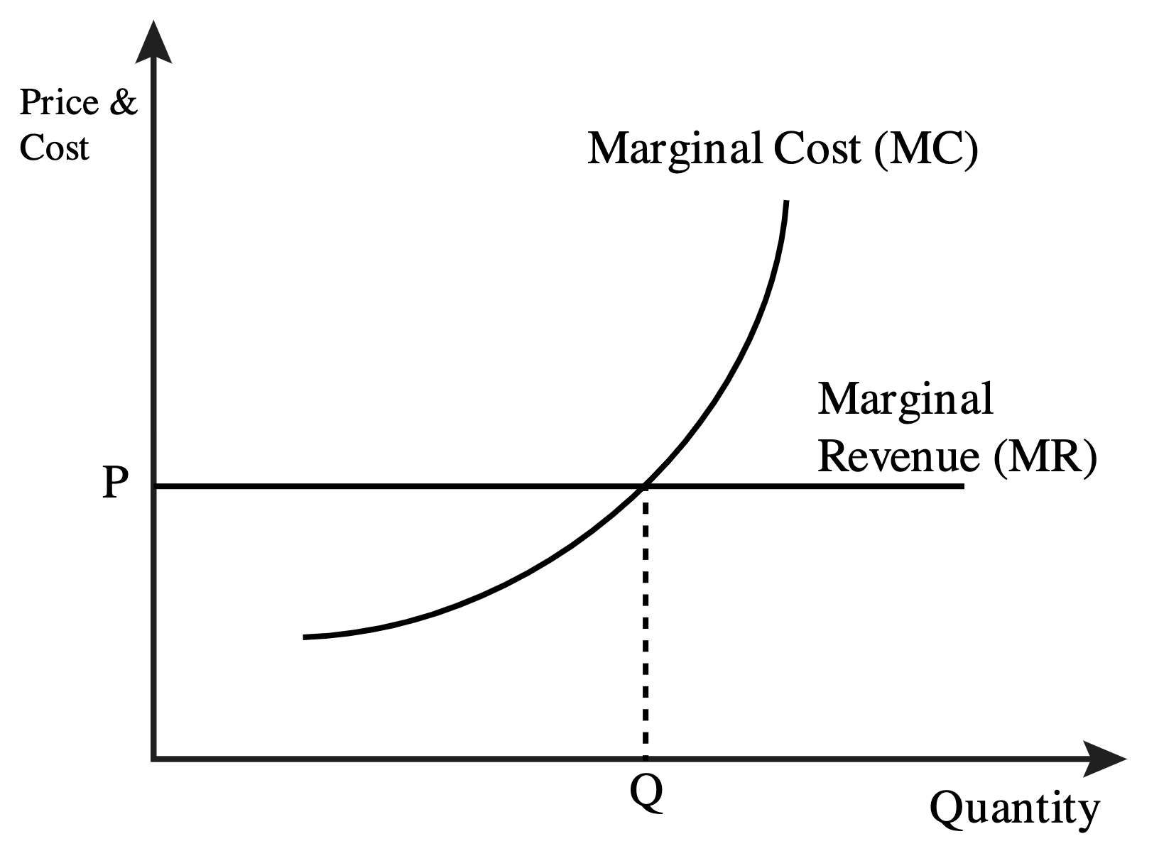
Image courtesy of OregonState.Education
Scenario: A company's profit (P) in thousands of dollars is modeled by the function , where represents the number of units produced and sold in thousands. Determine the number of units that must be produced and sold to maximize profit.
Solution:
First, we find the derivative of to identify the rate of change of profit with respect to the number of units. The maximum profit occurs where this derivative is zero.
Setting to find the critical point:
Conclusion: To maximize profit, the company must produce and sell units.
Application in Biology: Population Growth Rate
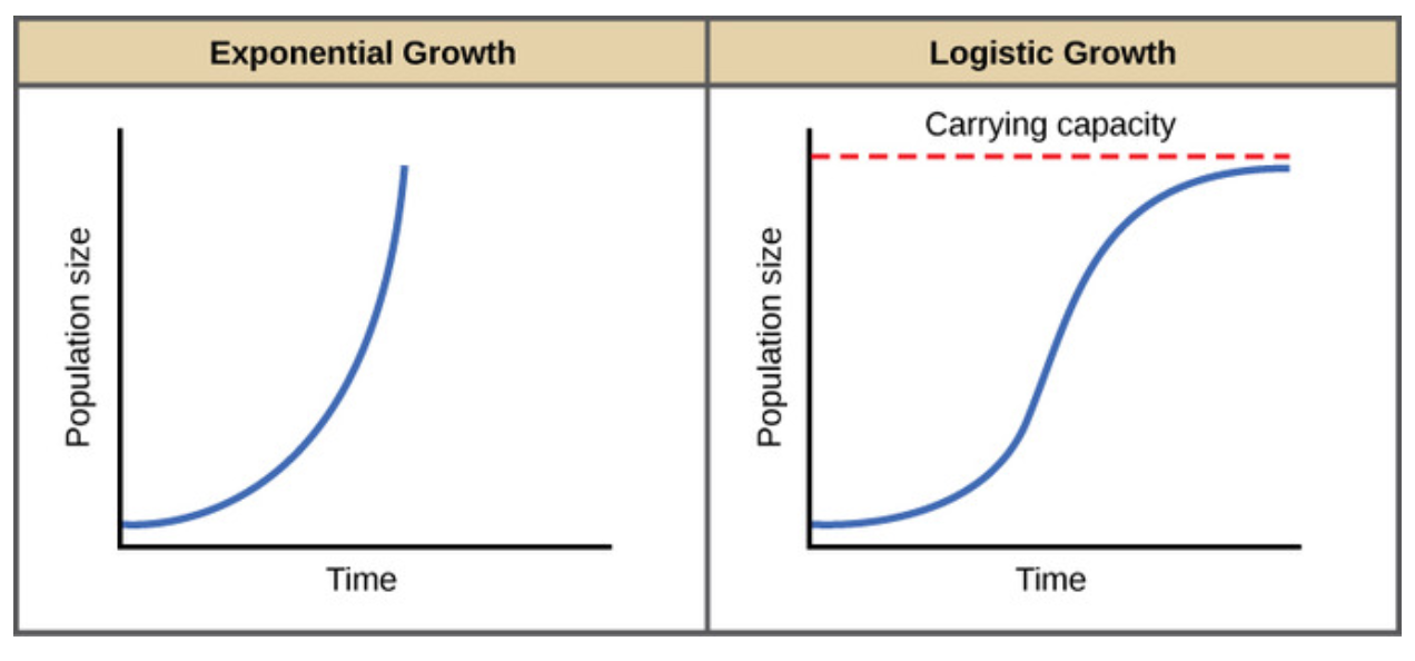
Consider a population of bacteria that grows according to the function , where is the population size and is time in hours.
Scenario: Determine the rate of population growth at hours.
Solution:
The growth rate is the derivative of with respect to :
Substitute to find the rate at that time:
Conclusion: The rate of population growth at hours is approximately bacteria per hour.
Chemical Kinetics: Rate of Reaction
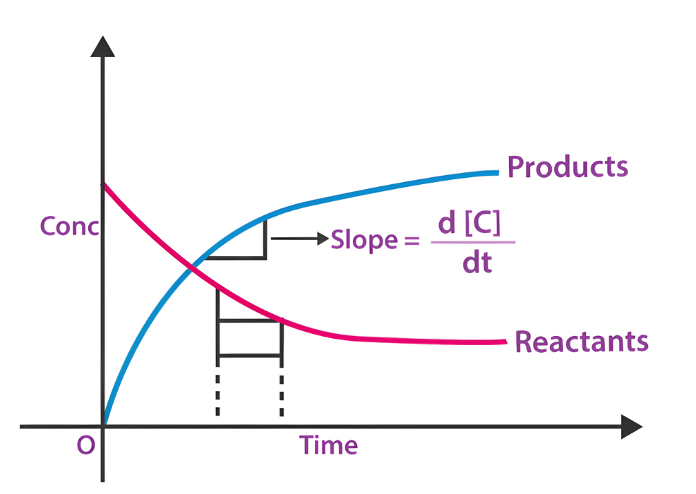
In a chemical reaction, the concentration of a reactant decreases over time according to the function , where is the concentration in moles per liter and is time in seconds.
Scenario: Find the rate of decrease of at seconds.
Solution:
The rate of decrease is the negative derivative of with respect to :
Substituting gives:
Conclusion: The rate of decrease in the concentration of at seconds is approximately moles per liter per second.
Practice Questions
Question 1
Evaluate the limit .
Question 2
A box with a square base and no top is to be made from a square piece of cardboard by cutting squares from each corner and folding up the sides. If the piece of cardboard is 12 inches on each side, what size square should be cut from each corner to maximize the volume of the box?
Solutions to Practice Questions
Solution to Question 1
1. Identify the Problem: Substituting directly into the function yields the indeterminate form , suggesting the need for simplification.
2. Simplify the Expression: Factor the numerator:
Cancel out the terms:
3. Evaluate the Limit: With the expression simplified, substitute :
Conclusion: The limit .
Solution to Question 2
1. Formulate the Problem: Define as the length of the side of the square cut from each corner. The dimensions of the box will be by by .
2. Volume Function: The volume is given by:
Simplify this to:
3. Find the Critical Points: Derive with respect to and set to 0 to find critical points:
Simplify and solve the quadratic equation:
Factoring:
yields or .
4. Determine the Maximum: By logical constraints, is the viable solution as would leave no material for the box sides.
5. Evaluate the Volume at : Substitute into the volume equation:
6. Conclusion: To maximize the volume, squares of 2 inches should be cut from each corner, yielding a box with a volume of 128 cubic inches.
Von Neumann Architecture
Von Neumann architecture is a computer design model that uses a single memory space to store both data and instructions, processed sequentially by the CPU.
Origins of the Von Neumann Architecture
The Von Neumann architecture was proposed by mathematician and physicist John von Neumann in the 1940s. It forms the foundational blueprint for most modern computers. Its central idea is to use a stored-program concept, meaning both the instructions (software) and data are held in the same memory and treated similarly. This design allows programs to be easily modified, saved, and reused.
The architecture simplifies computer design and is used in general-purpose computing systems ranging from desktop computers to smartphones.
Key Features of the Von Neumann Architecture
Single memory used for both data and instructions.
Instructions are processed sequentially (one after the other).
The CPU interacts with memory through a bus system.
Uses a Control Unit to manage the execution of instructions.
Operates based on the fetch-decode-execute cycle (covered in another subsubtopic).
The Von Neumann architecture includes several key components that allow it to function efficiently. These components are primarily a part of the CPU and the system memory.
Main Registers in Von Neumann Architecture
Memory Address Register (MAR)
The Memory Address Register (MAR) holds the memory address of the data or instruction that needs to be fetched or stored.
Purpose: Points to the location in memory the CPU wants to access.
Stores: Addresses only, never data.
Usage: During the fetch stage, the MAR is loaded with the address of the instruction the CPU wants to retrieve. The same applies during store operations when the CPU wants to write data to a specific memory address.
Example: If the CPU wants to access the instruction at memory location 205, MAR will contain the value 205.
Memory Data Register (MDR)
The Memory Data Register (MDR) stores the actual data that is being transferred to or from memory.
Purpose: Temporarily holds data that is being read from or written to the memory.
Stores: Data only, not addresses.
Usage:
When reading: MDR receives data fetched from the memory location specified by MAR.
When writing: MDR holds the data that will be written to the memory location specified by MAR.
Example: If the instruction at address 205 is LOAD A, 5, then MDR will hold the instruction LOAD A, 5 once it has been fetched.
Program Counter (PC)
The Program Counter (PC) keeps track of the memory location of the next instruction that the CPU should execute.
Purpose: Maintains the sequencing of program instructions.
Stores: Addresses only (specifically, of the next instruction).
Usage:
During the fetch stage, the PC provides the address of the next instruction to MAR.
After fetching, the PC is incremented so it points to the subsequent instruction, preparing the CPU for the next cycle.
Example: If the next instruction is at memory location 306, PC will contain the value 306.
Accumulator
The Accumulator is a special-purpose register that stores the results of arithmetic and logical operations performed by the CPU.
Purpose: Holds intermediate results, especially for arithmetic and logic operations.
Stores: Data only, usually numerical values.
Usage:
For a calculation like 5 + 3, the result (8) will be temporarily stored in the accumulator.
It allows quick access and manipulation of values without having to frequently access main memory.
Example: If the CPU performs an ADD 5 instruction to add 5 to the current value in the accumulator, and the accumulator previously contained 8, the updated value will be 13.
Interactions Among Registers
Each register works together as part of the CPU's operation cycle:
PC provides the address of the next instruction → loaded into MAR.
MAR sends the address to memory, and memory sends back the instruction → loaded into MDR.
The instruction in MDR is then decoded and executed by the Control Unit and ALU.
If the instruction involves calculations, the Accumulator is used to store results.
The PC is incremented to point to the next instruction in the sequence.
This cooperation allows the CPU to process instructions efficiently and systematically.
The Difference Between Storing Data and Storing an Address
Understanding the distinction between data and an address is critical when studying the Von Neumann architecture:
Data
Refers to the actual values or information used or manipulated during processing.
Stored in registers such as MDR and Accumulator.
Examples of data: numbers like 45, instructions like ADD 5, or results of calculations.
Address
Refers to the location in memory where data or instructions are stored.
Stored in registers such as MAR and PC.
Examples of addresses: 205, 306, or any memory location pointer.
Key Difference:
Data is what the CPU works with.
Addresses tell the CPU where to find or place that data.
Mixing these up can lead to serious processing errors. For example, mistakenly treating an address as data could cause the CPU to perform incorrect operations.
Practical Example: A Sample CPU Instruction Cycle
Let’s walk through a simplified cycle using the Von Neumann design to show how these components work together.
Step-by-step breakdown:
PC contains the address 101, where the next instruction is stored.
PC → MAR: MAR is loaded with the address 101.
MAR → memory: The CPU accesses the memory location 101.
Memory → MDR: The instruction (e.g., LOAD A, 10) at address 101 is transferred to MDR.
MDR → Control Unit: The instruction is sent for decoding and execution.
If LOAD A, 10 means load value 10 into the Accumulator:
The value 10 is stored in the Accumulator.
PC is incremented to 102 to prepare for the next instruction.
Each component contributes to efficient, step-by-step execution, forming the core mechanism of how a computer operates.
Summary of Key Registers and Their Roles
Below is a concise breakdown of the main registers within the Von Neumann architecture, what they store, and their purposes:
MAR
Stores: Address
Purpose: Holds the memory address to be accessed.
MDR
Stores: Data
Purpose: Temporarily holds data being transferred between memory and CPU.
Program Counter (PC)
Stores: Address
Purpose: Keeps track of the next instruction’s memory location.
Accumulator
Stores: Data
Purpose: Holds intermediate results of arithmetic/logical operations.
Benefits of the Von Neumann Architecture
While the GCSE syllabus does not require a deep evaluation of the architecture, understanding its design benefits helps students appreciate its wide adoption.
Simplifies CPU design by using a single memory system.
Reduces cost and complexity in building computers.
Makes programming easier due to uniform treatment of data and instructions.
Enables reusability and flexibility by storing programs in memory.
However, it also introduces the concept of the Von Neumann bottleneck, where the CPU can be slowed down by having to fetch data and instructions over the same bus. This is more relevant to advanced study, but is good to be aware of.
By mastering how these registers function within Von Neumann architecture, students gain a solid foundation in understanding how computers carry out instructions at the hardware level.
Sure! Here’s a simple Python example that simulates the fetch-decode-execute cycle using a basic representation of the Von Neumann architecture.
# Simulating a simple Von Neumann-style CPU
# Memory (storing both instructions and data)
memory = {
0: ('LOAD', 5),
1: ('ADD', 3),
2: ('SUB', 2),
3: ('STORE', 6),
4: ('HALT', None),
5: 10, # initial data
6: 0 # result will be stored here
}
# Registers
PC = 0 # Program Counter
MAR = None
MDR = None
ACC = 0 # Accumulator
# CPU cycle
def fetch():
global PC, MAR, MDR
MAR = PC
MDR = memory[MAR]
PC += 1
def decode_execute():
global MDR, ACC, memory
instruction, value = MDR
if instruction == 'LOAD':
ACC = memory[value]
elif instruction == 'ADD':
ACC += memory[value]
elif instruction == 'SUB':
ACC -= memory[value]
elif instruction == 'STORE':
memory[value] = ACC
elif instruction == 'HALT':
return False
return True
# Run the program
running = True
while running:
fetch()
running = decode_execute()
# Output final state of memory
print("Final value at memory[6]:", memory[6])
What This Does:
Memory stores both instructions and data (like Von Neumann design).
Registers simulate MAR, MDR, PC, and ACC.
The CPU goes through the fetch → decode/execute cycle until it hits a HALT instruction.
You’ll see the final result of the computation stored at memory address 6.
Let me know if you want a version with user input, file-based memory, or visualization!
1.1.4 Von Neumann Architecture
The Von Neumann architecture is a foundational design model for computers that uses a single memory and bus system for instructions and data.
What Is the Von Neumann Architecture?
The Von Neumann architecture, proposed by mathematician John von Neumann in the 1940s, describes a computer system where both program instructions and data share the same memory space and are processed by the Central Processing Unit (CPU). This model remains at the core of most modern general-purpose computers.
The architecture revolves around a control unit, an arithmetic logic unit (ALU), memory, input/output (I/O) devices, and a shared system bus for data movement. Key to this architecture are several important registers within the CPU that help control program flow and data handling.
Core Principles of Von Neumann Architecture
Single memory space: Both instructions and data reside in the same memory.
Sequential instruction execution: Instructions are carried out one after the other unless altered by a control flow instruction.
Use of registers: Registers store data temporarily for quick access and execution.
The fetch-decode-execute cycle: A continuous cycle that runs in the CPU to fetch an instruction from memory, decode it, and then execute it.
Key Registers in Von Neumann Architecture
Registers are small, fast memory units located within the CPU that temporarily store data or addresses. Each register has a specific role in the fetch-decode-execute cycle.
Memory Address Register (MAR)
The Memory Address Register (MAR) is crucial for accessing memory locations.
Purpose:
The MAR stores the address of the memory location that is to be read from or written to. It sends this address to the main memory to fetch or store data.
What It Stores:
Memory addresses only – not actual data.
Key Details:
When the CPU needs data or an instruction, the address of that data is placed into the MAR.
The MAR passes the address to the memory unit via the address bus.
The MAR does not store data itself — only the location where the data is found.
Example in Action:
If the CPU needs to access data located at memory address 0x004A, it will:
Place 0x004A into the MAR.
Send a request to memory using this address to retrieve or store the required data.
Memory Data Register (MDR)
The Memory Data Register (MDR) works closely with the MAR but serves a different function.
Purpose:
The MDR temporarily holds the actual data that is being transferred to or from memory.
What It Stores:
Data only – the actual contents retrieved from or sent to memory.
Key Details:
When reading from memory: Data from the memory location (pointed to by the MAR) is copied into the MDR.
When writing to memory: The CPU places the data to be stored in the MDR before it is written to memory.
The MDR interacts with the data bus to move data in or out of the CPU.
Example in Action:
If the CPU reads a value from memory address 0x004A, the MAR holds the address, and the MDR receives the value (e.g., 42) from that location.
Program Counter (PC)
The Program Counter (PC) plays a vital role in managing the sequence of instructions.
Purpose:
The PC stores the address of the next instruction to be executed.
What It Stores:
Memory addresses only – specifically, instruction addresses.
Key Details:
After fetching an instruction, the PC is automatically incremented to point to the next instruction.
If the current instruction is a jump or branch, the PC may be updated with a different address.
Keeps the CPU on track, ensuring correct execution flow of programs.
Example in Action:
If the current instruction is at address 0x0010, the PC holds 0x0010 and then increments to 0x0011 after the fetch stage.
Accumulator (ACC)
The Accumulator is one of the main working registers in the ALU (Arithmetic Logic Unit).
Purpose:
The accumulator stores intermediate results of arithmetic and logical operations performed by the CPU.
What It Stores:
Data only – specifically results of calculations or logic operations.
Key Details:
Results from operations like addition, subtraction, or logical AND/OR are stored in the accumulator.
Often used as both an input and output register during calculations.
Speeds up processing by avoiding the need to write temporary results back to memory.
Example in Action:
If the CPU is adding 7 + 5, the result (12) is stored in the accumulator, ready for further processing or output.
The Difference Between Storing Data and an Address
Understanding the difference between storing data and storing an address is essential to grasping how the Von Neumann architecture works.
Storing Data:
Involves holding actual values or information the CPU will use.
Examples: numbers like 10, characters like 'A', or binary results from logical operations.
Registers like the MDR and Accumulator store data.
Storing an Address:
Refers to holding the location in memory where data or instructions reside.
Think of it like holding the "home address" of a piece of data.
Registers like the MAR and Program Counter store addresses.
Why This Matters:
Incorrectly using data as an address, or vice versa, would result in errors or unexpected behavior.
Each register must be used for its intended purpose to maintain proper instruction execution.
The Fetch-Decode-Execute Cycle in Von Neumann Systems
The CPU operates in a repetitive cycle to run programs. Understanding this cycle highlights the roles of each register.
Step 1: Fetch
The PC holds the address of the next instruction.
That address is copied to the MAR.
The MAR sends the address to memory, and the instruction is fetched into the MDR.
The MDR then sends the instruction to the Current Instruction Register (CIR) (not detailed here).
The PC is incremented to point to the next instruction.
Step 2: Decode
The Control Unit (CU) decodes the instruction received from the MDR.
Step 3: Execute
The ALU performs operations using the instruction.
Any intermediate results are stored in the Accumulator.
If a memory operation is needed (like reading or writing), the MAR and MDR are used again.
This cycle continues repeatedly while the program runs, using the registers described to manage both data and addresses.
Summary of Register Roles
To reinforce the learning, here’s a breakdown of what each register does and what it stores:
Memory Address Register (MAR)
Purpose: Holds the memory location to access.
Stores: Address only.
Memory Data Register (MDR)
Purpose: Holds the data being transferred to or from memory.
Stores: Data only.
Program Counter (PC)
Purpose: Holds the address of the next instruction.
Stores: Address only.
Accumulator (ACC)
Purpose: Holds intermediate results of arithmetic/logical operations.
Stores: Data only.
Importance in Modern Computing
Despite being proposed over 80 years ago, the Von Neumann architecture is still a core concept in computing education and is used in most modern CPUs. Understanding the purpose of each register and the distinction between data and address is vital for:
Writing efficient programs.
Avoiding logical errors.
Understanding how high-level code is executed on hardware.
This foundational knowledge prepares students for more advanced topics in computer architecture, assembly language, and systems programming later in their studies.
Mock Questions
1. Describe the purpose of the Memory Address Register (MAR) and explain how it is used during the fetch stage of the fetch-decode-execute cycle. [6 marks]
The Memory Address Register (MAR) holds the address of the memory location that needs to be accessed. During the fetch stage, the Program Counter sends the address of the next instruction to the MAR. The MAR then places this address onto the address bus so the CPU can locate the instruction in RAM. The instruction at that memory address is fetched and sent to the Memory Data Register (MDR). The MAR only stores addresses and plays a critical role in ensuring that the correct memory location is accessed during program execution.
2. Explain the difference between storing data and storing an address, using two registers as examples. [6 marks]
Storing data means holding actual values used in processing, such as numbers or characters. Storing an address means holding the location in memory where data or an instruction is found. For example, the Accumulator stores data—specifically, the results of calculations. In contrast, the Program Counter stores the memory address of the next instruction to be executed. This distinction is important because using a data value where an address is needed—or vice versa—could cause errors. Each register must hold the correct type of value to ensure proper function during the fetch-decode-execute cycle.
FAQ
1. Why does the Von Neumann architecture use a single memory for both data and instructions, and what are the benefits and drawbacks of this design?
The Von Neumann architecture uses a single memory system for both instructions and data to simplify the computer’s design and reduce the number of hardware components. This design allows the same data and address buses to be used for fetching instructions and accessing data, which lowers manufacturing costs and makes it easier to build general-purpose computers. One key benefit is that it allows the system to be more flexible, as the memory can store any type of information needed by the program. However, a major drawback is known as the Von Neumann bottleneck. Since the CPU must access instructions and data using the same memory channel, it can only perform one memory operation at a time. This leads to performance limitations, especially in tasks requiring large amounts of data processing. Modern computing systems often include optimizations like caching and parallel pipelines to reduce this bottleneck while still using a Von Neumann-style approach.
2. What would happen if the MAR or MDR were used incorrectly during the fetch-decode-execute cycle?
If the MAR or MDR are used incorrectly during the fetch-decode-execute cycle, it can lead to serious errors that disrupt program execution. For example, if the MAR is given a data value instead of an address, the CPU will attempt to access a memory location that may not exist or is invalid, potentially causing the system to crash or behave unpredictably. Similarly, if the MDR is mistakenly given an address rather than data, the CPU may process meaningless information or fail to execute the instruction properly. The MAR must only store memory addresses, and the MDR must only store the actual data being transferred to or from memory. Mixing these up breaks the logic of the system. Since the control unit relies on the correct flow of address and data values between these registers and memory, any such error would result in incorrect instruction fetching, wrong memory access, or corrupted results during execution.
3. How does the accumulator improve the efficiency of arithmetic operations in the CPU?
The accumulator improves the efficiency of arithmetic operations by reducing the number of memory read/write operations needed during instruction execution. Instead of storing intermediate results back into RAM after every operation, the CPU uses the accumulator to hold these temporary values directly within the processor. This makes operations like repeated additions or chained calculations significantly faster, as accessing data from a register like the accumulator is much quicker than accessing main memory. The accumulator works closely with the Arithmetic Logic Unit (ALU), which performs the actual operations. For example, in a calculation involving several additions, the result of the first addition is stored in the accumulator, then used in the next addition without returning to memory. This approach speeds up processing and reduces bus traffic. By minimizing memory usage and keeping results close to the ALU, the accumulator plays a key role in optimizing performance within a Von Neumann system.
4. Can the Program Counter (PC) ever be modified manually by a program, and if so, why would this be done?
Yes, the Program Counter (PC) can be modified manually by certain types of instructions in a program, typically jump, branch, or call instructions. These instructions deliberately change the value of the PC so that the CPU will fetch the next instruction from a different memory location instead of continuing sequentially. This is essential for creating loops, conditional execution, and function calls. For example, in a loop structure, the program may need to return to a previous instruction if a condition is still true. The PC is then updated with the address of that instruction. In function calls, the PC is modified to jump to the function’s memory location and later restored to continue from where it left off. This ability to modify the PC is a fundamental feature of control flow in programming. Without it, all programs would execute instructions in a straight line with no decision-making or repetition.
5. How are the MAR and MDR involved in write operations, and what is the sequence of events during a memory write?
During a memory write operation, the MAR and MDR work together to ensure that the correct data is stored in the correct memory location. First, the CPU places the address where the data needs to be written into the Memory Address Register (MAR). At the same time, the Memory Data Register (MDR) is loaded with the actual data to be written. Once both registers are set, the control unit sends a write signal to the memory. The memory system then writes the data from the MDR into the memory address specified by the MAR. The sequence of events is: 1) load address into MAR, 2) load data into MDR, 3) activate write control signal, and 4) complete the write by transferring data into memory. This operation ensures that data goes to the correct location, which is essential for maintaining program correctness and reliable system behavior. Mistakes in this process could lead to overwritten or lost data.
