
AP Syllabus focus: ‘Forces are drawn as vectors from the center of mass, treating the system as if all mass were concentrated there.’
For translational dynamics, forces are represented as vectors acting on a simplified object model. Drawing all forces from the center of mass makes the diagram clearer and correctly connects external forces to the system’s acceleration.
Why forces are drawn from the center of mass
In AP Physics 1, many problems focus on translation (how the object’s velocity changes) rather than rotation.
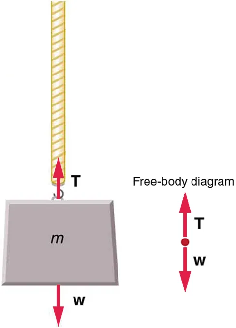
Free-body diagram of a mass hanging from a rope, showing the tension force upward and the weight downward as vectors applied to a simplified point-object model. This illustrates the modeling convention that forces are drawn on the object representation (often taken at the center of mass) to analyze translational motion. Source
A force diagram is then a model: you treat the object or system as if its entire mass is concentrated at one point, the center of mass, and you attach the force vectors there.
This convention helps you:
Keep the diagram uncluttered
Emphasize that forces are vectors (they have magnitude and direction)
Connect the force picture directly to center-of-mass acceleration
Center of mass (what point you are using)
Center of mass: The mass-weighted average position of an object or system; the point where the system can be modeled as if all its mass were concentrated for translational motion.
Even if forces physically act at different locations (a push on one side, friction along a surface), for translation-focused analysis you typically draw them as if they act at the center of mass.
What a “force vector from the center of mass” means
Drawing a force from the center of mass is a representation choice, not a claim about where the force is applied. It means:
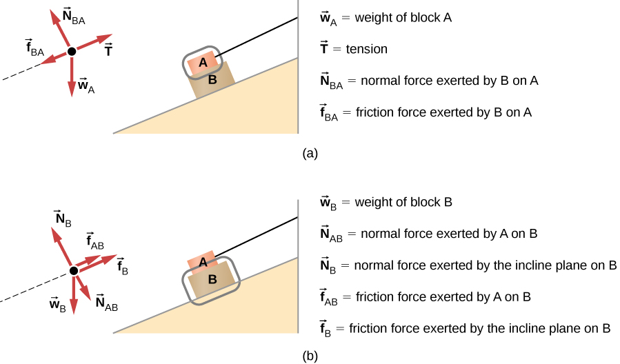
Free-body diagram for a block on an incline, with forces (tension, normal force, friction, and weight) drawn as vectors on the isolated object. The diagram makes the “one object/system, only external forces” rule concrete and sets up component-based use of Newton’s second law, e.g., along the slope. Source
The force is an external interaction on the chosen object/system.
The force contributes to the net external force that determines the acceleration of the center of mass.
The tail of each force arrow starts at the center-of-mass point in the diagram.
What it does NOT mean (common misconceptions)
It does not mean all forces actually act at the center of mass in real life.
It does not mean contact forces ignore where the contact occurs; it only means your current model is not tracking rotational effects.
It does not mean internal forces belong on the diagram (they do not, because they are not exerted by the environment on the chosen system).
Using the center-of-mass model to write Newton’s second law
Once all external forces are drawn as vectors from the center of mass, you can sum components to relate them to acceleration.
= net external force in the -direction, in N
= total mass of the object or system, in kg
= acceleration of the center of mass in the -direction, in
= net external force in the -direction, in N
= acceleration of the center of mass in the -direction, in
This is why the “all forces from the center of mass” convention is so useful: it matches the idea that the net external force determines the center-of-mass acceleration.
Practical diagram rules for this subsubtopic
How to place the vectors
Mark a dot (or small cross) for the center of mass.
Draw each external force as an arrow starting at that dot.
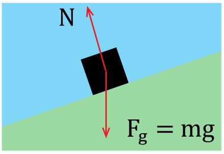
Diagram showing the normal force on an object on an inclined surface, drawn perpendicular to the surface rather than vertical. This helps students correctly orient contact forces in a simplified center-of-mass free-body diagram before writing component equations. Source
Label each force clearly (for example, weight , normal , tension ), keeping labels close to the arrow.
How to treat systems
If your “object” is actually a system (multiple objects considered together), still draw forces from the system’s center of mass:
Include only forces exerted by the environment on the system.
Exclude forces that objects in the system exert on each other (those are internal).
When the convention can break down
If the problem’s goal involves whether the object tips, rotates, or pivots, the location where forces act matters. In that case, drawing all forces at the center of mass is no longer sufficient by itself (you would need a model that includes where forces are applied).
Practice Questions
Q1 (2 marks) A block is pulled to the right across a horizontal surface by a rope. State where you should draw the force vectors on the free-body diagram and briefly explain why.
1 mark: Forces drawn as vectors from the block’s centre of mass (or a single point representing it).
1 mark: Explanation that this treats the block as a single-object model for translational motion (all mass concentrated at the centre of mass / relates net force to COM acceleration).
Q2 (5 marks) Two carts, A and B, are in contact on a frictionless track and are pushed to the right by an external horizontal force applied to cart A. You choose the system to be both carts together. (a) On a free-body diagram for the system, state which horizontal forces should be shown. (2 marks) (b) State where these forces should be drawn and why. (2 marks) (c) Write the equation relating to the system’s acceleration . (1 mark)
(a)
1 mark: Include the external applied force acting on the system.
1 mark: Exclude the contact force between A and B as it is internal to the system.
(b)
1 mark: Forces drawn from the system’s centre of mass (single point).
1 mark: Reason: system model treats all mass as concentrated there for translational analysis / net external force gives COM acceleration.
(c)
1 mark: (or with ).
FAQ
Because the diagram is modelling translation only: it tracks how the centre of mass accelerates under the net external force.
If rotation is relevant, the point of application affects turning, and this simplification may not be sufficient.
Use the best single-point approximation your model allows (often the geometric centre is used in sketches).
The key is consistency: all external force vectors originate from the same chosen COM point for that object/system.
Yes, if you choose to resolve it. Draw the original force from the COM, then optionally draw its perpendicular components from the same point.
Keep components clearly labelled to avoid double-counting.
No. It changes only the representation. The real forces still act at their contact locations; the COM drawing is a modelling convention for translational dynamics.
Look for cues about rotation (tipping, pivoting, angular acceleration, “about a point,” or stability). If none appear and the focus is on $a$ or $v$, the COM convention is typically intended.
