
AP Syllabus focus: 'The electric field is a vector quantity represented in space using vector field maps. The net electric field is the vector sum of individual electric fields.'
Understanding electric field as a vector is essential because both magnitude and direction matter at every point in space, especially when several charged objects influence the same location.
Electric field as a vector quantity
An electric field must be treated as a vector, not just a number. That means it has both a magnitude and a direction at every point in space.
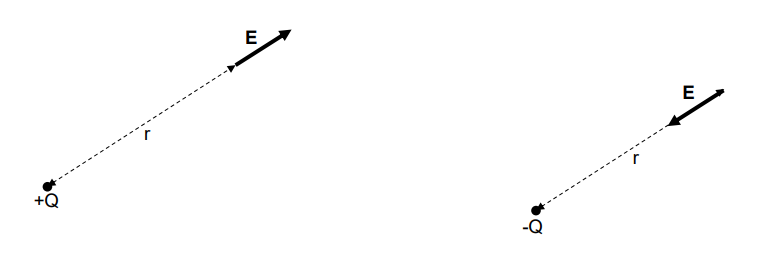
Electric-field direction around isolated point charges. The diagram shows that a positive source charge produces field vectors pointing radially outward, while a negative source charge produces vectors pointing radially inward, emphasizing that is defined with both magnitude and direction at each point. Source
When describing the field at a location, you must state how strong it is and which way it points.
A scalar quantity can be added with ordinary arithmetic, but a vector quantity must be combined using vector rules. This is why electric field problems often require attention to direction, signs, and geometry, not just numerical values.
Vector quantity: A physical quantity that has both magnitude and direction.
Because the electric field is a vector, two fields of equal magnitude can produce very different results depending on their directions. If they point in the same direction, the overall field becomes stronger. If they point in opposite directions, they partially or completely cancel.
This idea is central to understanding how multiple charged objects affect the same location. The field at a point is never determined by one source alone if other sources are also present.
Representing electric fields in space
A field exists throughout a region of space, so it is useful to show it with a map. A vector field map places arrows at selected points.
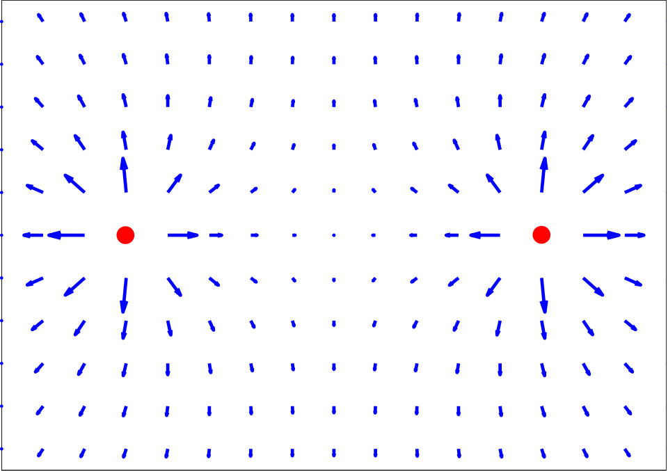
Vector field map (quiver plot) for two equal positive point charges. The arrow direction gives the local electric-field direction at each point, while the arrow length indicates relative field magnitude, showing how the field varies across space when multiple sources are present. Source
Each arrow represents the electric field at that exact location.
Vector field map: A representation of a field in space using arrows whose direction shows the field direction and whose size shows the field magnitude.
A vector field map helps visualize how the electric field changes from place to place. On such a map:
the direction of each arrow shows the direction of the electric field at that point
the length of the arrow shows the relative magnitude of the field
arrows at different positions may point in different directions because the field can vary across space
A vector field map is always interpreted point by point. Each arrow gives local information about one location only. You should not assume that one arrow describes the entire region.
The map also makes it easier to compare different locations. Longer arrows indicate stronger electric fields, while shorter arrows indicate weaker ones. If nearby arrows change direction significantly, the field changes rapidly across that region.
Net electric field and vector addition
When more than one charged object contributes to the field at a point, the result is called the net electric field. Since electric field is a vector quantity, the net field is found by adding the individual field vectors.
Net electric field: The overall electric field at a point found by taking the vector sum of all individual electric fields at that point.
This process is called vector superposition. Each source creates its own electric field, and the combined effect is found by adding those fields as vectors. The key phrase is at that point: all of the individual field vectors must be evaluated at the same location before they are added.
= net electric field at a chosen point, in newtons per coulomb
= individual electric field vectors from different sources at that same point, in newtons per coulomb
If the individual fields lie along the same line, the addition can be handled with signed values. If they are at angles, standard vector addition must be used. In many AP Physics 2 Algebra situations, this means resolving the vectors into perpendicular components and adding the components separately.
This is why the phrase vector sum is so important. You cannot simply add magnitudes unless all the vectors point in exactly the same direction. Direction changes the result.
How vector maps show superposition
A vector field map of a system with multiple charges is built from the net electric field, not from one source alone. At each plotted point, you imagine all contributing field vectors there and combine them to get one final arrow.
This means a map can show patterns such as:
regions where arrows become larger because contributions reinforce each other
regions where arrows become smaller because contributions oppose each other
points where the net field may be zero because the vector sum cancels
A zero net field at one location does not mean there is no electric field everywhere nearby. It only means that, at that particular point, the contributing vectors balance exactly.
Because the field is a vector quantity, the overall map can be quite different from what you would predict by looking only at distances or only at magnitudes. Direction must always be included.
Common interpretation tips
When reading or drawing a vector field map, keep these ideas in mind:
always identify the field at a specific point
compare both arrow direction and arrow length
add electric fields using vector rules, not ordinary scalar addition
if vectors are perpendicular, treat their horizontal and vertical parts separately
the net field depends on all sources acting together
a single diagram can represent a field that changes continuously across space, even though only selected points are shown
Careful use of vector language makes electric field maps much more meaningful. In AP Physics 2 Algebra, this supports both conceptual reasoning and correct calculation when several electric fields act at once.
Practice Questions
At point , one charged object produces an electric field of to the east, and another produces an electric field of to the north.
Determine the magnitude and direction of the net electric field at point . [3 marks]
1 mark for recognizing that the two electric fields must be added as perpendicular vectors
1 mark for correct magnitude:
1 mark for correct direction: about north of east
Three charged objects create electric fields at point as follows:
east
west
north
(a) Determine the horizontal component of the net electric field at . [1 mark]
(b) Determine the vertical component of the net electric field at . [1 mark]
(c) Calculate the magnitude of the net electric field at . [2 marks]
(d) State the direction of the net electric field relative to east. [1 mark]
(e) Explain how the vector field arrow at point should appear on a vector field map compared with an arrow at a point where the net field is half as large but points in the same direction. [1 mark]
(a)
1 mark for east
(b)
1 mark for north
(c)
1 mark for using vector combination, such as
1 mark for correct magnitude: about
(d)
1 mark for correct direction: about north of east
(e)
1 mark for stating that the arrow at should point in the same direction but be twice as long, assuming the map uses a consistent scale
FAQ
A real electric field exists at every point in space, but drawing an arrow everywhere would make the map unreadable.
A map samples the field at enough locations to show the pattern clearly. The physics does not change between those points; the drawing is just a simplified representation.
Yes. Many different source configurations can give the same net electric field vector at a single location.
That is because a single vector contains limited information: one magnitude and one direction. It does not uniquely identify the number, position, or value of the sources that produced it.
Software often rescales arrows so the map stays readable.
Common choices include:
limiting the longest arrows
enlarging short arrows so they remain visible
using relative rather than exact lengths
Because of this, always check whether the map includes a scale or a note about normalization.
Yes. The actual electric field usually changes continuously from point to point in space.
A map may look jumpy because it only shows arrows at discrete locations. If more sample points were added, the pattern would usually appear smoother.
Vector components depend on the chosen axes, but the final net vector does not.
This means you are free to select axes that make the math easier, such as:
horizontal and vertical axes
axes parallel and perpendicular to one known field vector
A smart axis choice can reduce algebra without changing the physical result.