
AP Syllabus focus: 'A free-body diagram shows all forces exerted on one object or system by the environment. Each force is drawn as a separate straight arrow from the center of mass.'
Free-body diagrams are the foundation of mechanics analysis. A careful diagram makes the chosen system explicit, isolates external interactions, and helps prevent missing forces, double-counting, and direction errors before equations are written.
Core purpose of a free-body diagram
A free-body diagram represents a single chosen object or a single chosen system after it has been mentally separated from everything around it.
Free-body diagram: A simplified sketch of one chosen object or system showing every external force acting on it, with each force represented by a separate arrow.
The key idea is that the diagram is not a picture of the whole situation. It is a force map for only the object or system being analyzed. Everything outside that choice belongs to the environment, and any force shown on the diagram must come from that environment.
Because the diagram focuses on forces, it should be simple and uncluttered. The object is often drawn as a box, dot, or basic shape. Details such as texture, motion path, or surrounding objects are usually omitted unless they help identify a force source.
Essential rules for accuracy
Choose one object or one system
Start by deciding exactly what is being analyzed.
If you choose a single object, show only forces exerted on that object by other objects.
If you choose a system of multiple objects, show only forces exerted on the entire system by the outside world.
This choice matters because a force can be external for one diagram and absent from another. For example, a force between two objects inside the same chosen system is not shown as an external force on the system-level free-body diagram.
A common mistake is to switch systems midway through the diagram. Once the object or system is chosen, every force shown must match that choice.
Show all external forces, and only external forces
A correct diagram includes every force exerted on the chosen object or system by the environment.
Typical forces may include:
Gravitational force
Normal force
Tension
Applied force
Friction
Drag or air resistance
Do not include anything that is not actually a force. In particular, do not draw:
velocity arrows
acceleration arrows
motion directions
path shapes
“force of motion”
internal forces within the chosen system
The diagram should show real interactions, not what the object is “trying” to do.
Draw each force as a separate straight arrow
Each force must appear as its own arrow. Do not combine several forces into one arrow unless you are specifically replacing them with a known resultant, which is usually not what a free-body diagram is for at the start of a problem.
Separate arrows make it possible to identify each interaction clearly.
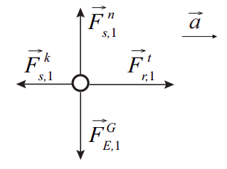
Single-object free-body diagram of a block showing multiple external forces drawn as separate vectors from the object’s representative point. The figure illustrates how normal force and weight can balance vertically while the horizontal forces differ, producing a net force and acceleration. This is a compact model for translating an interaction picture into a force map suitable for . Source
They also make later vector addition and Newton’s second law applications much more reliable.
A related mistake is drawing one force and then also drawing its components on the same diagram. A force and its components are two ways of representing the same interaction, so they should not both appear together unless the original force is removed and replaced by the components.
Start each arrow at the center of mass
For AP Physics C Mechanics free-body diagrams, each force is drawn as a straight arrow from the center of mass of the chosen object or system.
This convention keeps the diagram standardized and readable. Even when a real contact force acts at a surface, the simplified free-body diagram places the arrow at the center of mass to represent the overall effect of that external interaction on translational motion.
The center of mass is therefore the standard reference point from which force arrows begin in this type of diagram.
Label every force clearly
A diagram is only useful if each arrow can be identified. Labels should indicate the type of force, and when possible the source of that force.
Good labels are more informative than vague ones. For instance, “normal force from table on block” is better than simply “upward force.” Clear labels reduce confusion when multiple forces have similar directions.
What belongs on the diagram and what does not
A good free-body diagram is selective. It includes forces acting on the chosen object or system, not forces exerted by it on something else.
That means Newton’s third-law partner forces are not placed on the same single-object free-body diagram, because those partner forces act on different objects.
Also, the net force is usually not drawn as an additional force arrow. The net force is the vector sum of the actual external forces already shown. Drawing it separately as if it were another interaction can lead to double-counting.
Getting force directions right
Direction is just as important as force identification.
Gravitational force points toward Earth, which is usually straight downward near the surface.
Normal force is perpendicular to the contact surface, not always vertical.
Tension points along the string, rope, or cable, away from the object.
Friction is parallel to the contact surface and opposes relative motion or the tendency for relative motion.
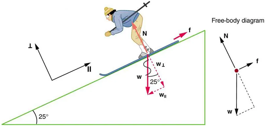
Inclined-plane free-body diagram (skier on a slope) showing weight , normal force , and friction , with the weight decomposed into components parallel and perpendicular to the surface. This is a standard example of choosing axes aligned with the surface so that the normal force is purely perpendicular while friction is purely parallel. The diagram makes it visually obvious why the normal force is not generally vertical on a slope. Source
Drag points opposite the object’s motion through a fluid.
If the direction is uncertain, think about the specific interaction causing the force rather than relying on memorized arrow patterns.
Common mistakes to avoid
Drawing forces from the edge of the object instead of from the center of mass
Leaving out a force because the object is moving at constant speed or is momentarily at rest
Adding a “centripetal force” or “force of acceleration” instead of identifying the real forces
Showing both a force and its x- and y-components on the same diagram
Including forces the chosen object exerts on other objects
Mixing two different objects into one diagram without explicitly defining the system
Using curved arrows or sketchy lines instead of distinct straight arrows
An accurate free-body diagram is a disciplined representation of external interactions. If the chosen system is clear, every external force is present, and each one is shown as a separate straight arrow from the center of mass, the diagram is doing its job.
FAQ
Usually, no. A free-body diagram is primarily about which forces act and in what directions.
If a problem or teacher specifically asks for a scaled diagram, then relative arrow lengths should reflect magnitude. Otherwise, neatness and correct labelling matter more than exact length.
That said, wildly misleading arrow sizes can confuse your later reasoning, so it is sensible to make obviously larger forces look larger when that is known.
An interaction diagram lists which objects interact with the chosen object or system. A free-body diagram comes after that and shows only the forces from those interactions.
A useful workflow is:
choose the object
list interacting objects
convert each relevant interaction into a force on the free-body diagram
This helps reduce missed forces.
Draw multiple diagrams when you need separate equations for different objects or subsystems.
This is especially helpful when:
objects can accelerate differently
you need an unknown contact force or tension
one combined system hides an internal force you later need
Each diagram must correspond to one clearly defined choice of system.
If you choose a non-inertial frame, you may need to include a fictitious force so that Newton’s laws can still be applied in that frame.
On AP Physics C, most introductory free-body diagrams are made in inertial frames unless the question clearly signals otherwise.
If you do use a non-inertial frame, label the extra force very clearly so it is not mistaken for a real interaction.
For pure translational analysis, AP-style free-body diagrams often place all forces at the centre of mass for clarity.
If rotation or torque matters, the actual line of action and point of application can become important. In that case, a more detailed rigid-body sketch may be needed alongside the usual force diagram.
So the simplified diagram is not wrong; it is just designed for a particular purpose.
Practice Questions
A block slides to the right across a rough horizontal surface after being given an initial push. State the forces that should appear on the block’s free-body diagram after the push is no longer in contact with the block.
1 mark: gravitational force downward
1 mark: normal force upward from the surface
1 mark: friction force to the left
A box is pulled across a rough floor by a rope that makes an angle above the horizontal. A student draws a free-body diagram for the box that includes weight, normal force, tension, friction, velocity to the right, and a net force arrow.
(a) Identify the two items that should not appear on the free-body diagram. (2 marks)
(b) Describe the correct direction of each actual force that should remain on the diagram. (3 marks)
(a)
1 mark: velocity should not appear
1 mark: net force arrow should not appear as an additional force
(b)
1 mark: weight acts downward
1 mark: normal force acts upward, perpendicular to the floor
1 mark: tension acts along the rope upward and to the right, and friction acts to the left along the floor
Award this mark only if both tension and friction directions are correct
