
OCR Specification focus:
‘Resistance R = V ÷ I; Ohm’s law for ohmic conductors at constant temperature.’
Resistance is a fundamental concept in electricity that determines how difficult it is for electric current to flow through a material. Understanding resistance and Ohm’s law is essential for analysing, designing, and interpreting electrical circuits accurately.
Resistance: The Core Concept
Definition of Resistance
Resistance: The opposition to the flow of electric current in a component or conductor.
Resistance quantifies how much a material or device resists the movement of charge carriers (typically electrons) when a potential difference (p.d.) is applied across it. The higher the resistance, the smaller the current for a given potential difference.
Relationship Between Potential Difference and Current
In an electrical circuit, the potential difference (V) across a component drives an electric current (I) through it. The relationship between these quantities and resistance (R) is given by Ohm’s law.
EQUATION
—-----------------------------------------------------------------
Ohm’s Law (R = V ÷ I)
V = potential difference across the component (volts, V)
I = current through the component (amperes, A)
R = resistance of the component (ohms, Ω)
—-----------------------------------------------------------------
This equation allows calculation of one of the three quantities—V, I, or R—when the other two are known.
Ohm’s Law and Ohmic Conductors
Statement of Ohm’s Law
Ohm’s Law: For a metallic conductor kept at constant temperature, the current is directly proportional to the potential difference across it.
In simpler terms, doubling the potential difference doubles the current, provided that temperature and other physical conditions remain constant.
Ohmic and Non-Ohmic Behaviour
A conductor that obeys Ohm’s law is called an ohmic conductor. Such materials show a linear relationship between current and potential difference.
Ohmic conductors: Metals such as copper and aluminium at constant temperature.
Non-ohmic conductors: Components like filament lamps or diodes, where current and voltage are not directly proportional.
The distinction between ohmic and non-ohmic materials is critical for interpreting I–V characteristics, though the quantitative analysis of curves belongs to a later subsubtopic.
Understanding the Resistance of Materials
Factors Affecting Resistance
Resistance depends on several physical and environmental factors:
Length (L): A longer conductor provides more collisions for charge carriers, increasing resistance.
Cross-sectional area (A): A thicker conductor allows more charge flow, reducing resistance.
Material type: Different materials have different resistivities, a property linked to their atomic structure.
Temperature: For metals, resistance generally increases with temperature because atoms vibrate more, scattering electrons more frequently.
These factors underpin the relationship explored later in resistivity, but for Ohm’s law, temperature control is the crucial element.
Constant Temperature Condition
Importance of Temperature Control
The phrase “at constant temperature” in the specification is vital. For Ohm’s law to hold, the material’s resistivity must remain unchanged. In metals, heating leads to increased lattice vibrations, hindering electron flow and causing deviation from proportionality between V and I.
Maintaining a stable temperature ensures that any change in current is due solely to changes in potential difference, not thermal effects. In laboratory settings, low currents or short connection times are used to prevent components from heating.
Observing Deviations
If temperature is not constant, the graph of V against I curves rather than remaining straight. This indicates that resistance is changing — a key diagnostic feature in experimental contexts.
Measuring Resistance Practically
Basic Circuit Setup
To determine resistance experimentally, students typically use a simple circuit containing:
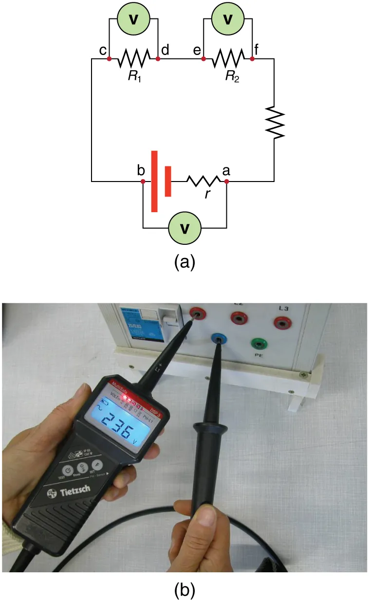
Voltmeter (V) connected in parallel with the component to measure the potential difference across it. This layout ensures the meter experiences the same p.d. as the component. The diagram also shows the source’s internal resistance (extra detail not required by the syllabus but harmless for context). Source.
A power supply providing a variable potential difference,
The component under test (such as a resistor),
An ammeter in series to measure current,
A voltmeter connected in parallel to measure potential difference.
By varying the applied voltage and recording the corresponding current, one can calculate the resistance using Ohm’s law.
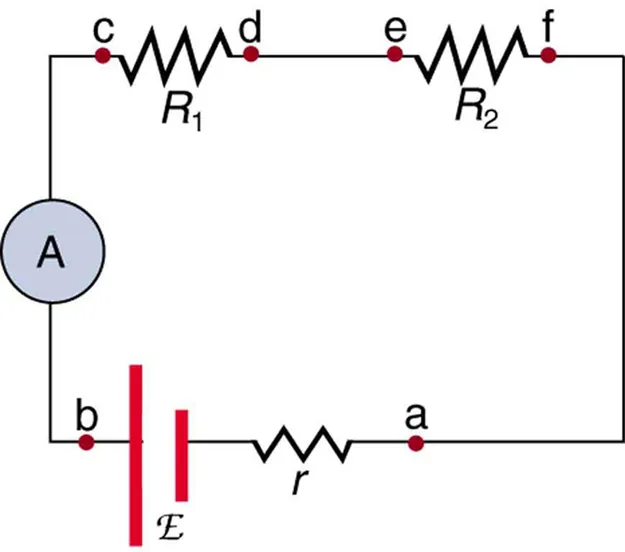
Ammeter (A) in series so that the entire branch current flows through the meter. With sufficiently low ammeter resistance, the circuit is minimally disturbed. The figure includes source emf and internal resistance (extra detail beyond the syllabus core). Source.
Calculating Resistance
EQUATION
—-----------------------------------------------------------------
Resistance from Measurements (R = V ÷ I)
V = measured potential difference (V)
I = measured current (A)
R = calculated resistance (Ω)
—-----------------------------------------------------------------
Once measurements are taken, plotting a graph of V against I allows students to verify Ohm’s law. A straight line through the origin confirms proportionality and thus ohmic behaviour.

Current–voltage characteristic of an ohmic resistor: the straight line through the origin indicates I ∝ V and constant resistance. The slope corresponds to 1/R on an I–V plot (or R on a V–I plot). This is the canonical graphical signature of Ohm’s law at constant temperature. Source.
Graphical Interpretation
V–I and I–V Graphs
In ohmic conductors:
The V–I graph is a straight line passing through the origin.
The gradient of the line represents the resistance (R = V/I).
Alternatively, plotting I against V gives a line whose gradient equals 1/R. These graphical methods provide visual evidence of the law’s validity and help identify any non-linear effects due to temperature changes or component characteristics.
Experimental Accuracy
To improve precision in experiments:
Use digital meters to reduce parallax and reading errors.
Ensure good electrical connections to minimise contact resistance.
Maintain a constant ambient temperature and avoid prolonged current flow.
Repeat measurements and calculate mean values for reliability.
Such good practice ensures results truly reflect Ohm’s law rather than measurement artefacts.
Conceptual Applications
Practical Importance of Resistance and Ohm’s Law
Understanding resistance and Ohm’s law underpins nearly all circuit analysis, including calculations of power (P = VI) and energy transfer (W = VIt) in later topics. Designers use resistance values to control current, limit energy loss, and ensure safety in electrical systems.
Real-World Examples
Although not explored quantitatively here, the principles of resistance apply to devices such as:
Resistors: providing fixed resistance values to control circuit behaviour.
Sensors: thermistors and LDRs where resistance varies with environmental conditions.
Wires and cables: chosen based on resistivity and resistance to minimise energy loss.
These illustrate how the simple relationship R = V ÷ I governs the design, testing, and functionality of countless electrical and electronic systems.
Practice Questions
Question 1 (2 marks)
State Ohm’s law and explain the condition under which it applies to a conductor.
Mark scheme:
1 mark for correctly stating Ohm’s law: The current through a conductor is directly proportional to the potential difference across it.
1 mark for specifying the condition: The temperature (and other physical conditions) of the conductor must remain constant.
Question 2 (5 marks)
A student investigates the relationship between current and potential difference for a metal wire. The student records several pairs of current and potential difference readings and plots a straight-line graph through the origin.
a) Explain what the straight-line graph indicates about the behaviour of the metal wire. (2 marks)
b) Describe two factors that could cause the wire to deviate from this linear relationship during the experiment. (2 marks)
c) Suggest one method the student could use to reduce the effect of these factors. (1 mark)
Mark scheme:
a)
1 mark: The straight line through the origin shows that current is directly proportional to potential difference.
1 mark: Therefore, the wire obeys Ohm’s law and behaves as an ohmic conductor.
b)
1 mark: Temperature rise in the wire increases lattice vibrations, increasing resistance and causing deviation.
1 mark: Poor connections or variable contact resistance could also affect linearity.
c)
1 mark: Keep current low or use short measurement intervals to prevent heating, maintaining constant temperature.
FAQ
As temperature rises, metal atoms vibrate more vigorously around their fixed positions in the lattice.
This increased vibration makes it more difficult for electrons to move through the metal, as they collide more frequently with the vibrating atoms.
These collisions reduce the average drift velocity of the electrons for a given potential difference, resulting in an increase in resistance.
This microscopic explanation accounts for why metallic conductors deviate from Ohm’s law when heated.
Ohm’s law only applies when the relationship between current and potential difference remains linear and passes through the origin.
Some components, such as diodes and filament lamps, show non-linear behaviour because their resistance changes with voltage or temperature.
In these devices:
Filament lamps: Heating causes resistance to rise, producing a curved I–V graph.
Diodes: Current flows easily in one direction but very little in the reverse, producing a sharply non-linear curve.
Thus, Ohm’s law is a special case, not a universal rule.
When charge carriers move through a resistor, they collide with atoms in the conductor.
Each collision transfers energy to the lattice as heat, leading to energy dissipation.
This process explains why resistors warm up during operation.
The rate of energy transfer (power) is given by P = I²R, showing that higher resistance or current leads to greater heating.
In practical design, managing resistance is crucial to avoid unwanted energy loss or overheating.
The proportional relationship between current and potential difference only holds if resistance stays constant.
Since resistance in a metal depends on temperature, any heating of the conductor changes its resistance.
To maintain constant temperature:
Use small currents or short testing durations.
Allow the conductor to cool between readings.
Avoid high-resistance wires that heat easily.
If temperature rises, the experimental data curve deviates from linearity, making the verification of Ohm’s law invalid.
Superconductors behave differently — rather than following Ohm’s law, they exceed it by having zero resistance below a critical temperature.
In this state, current flows indefinitely without energy loss, meaning potential difference and resistance both drop to zero.
This condition is not a proportional V–I relationship; instead, it represents a complete breakdown of Ohm’s law’s assumptions.
Superconductivity, while related to resistance, belongs to a more advanced domain beyond ordinary ohmic behaviour.
