
OCR Specification focus:
‘Manage risk using power supplies; avoid overheating components; measure V and I accurately.’
Ensuring safety and measurement accuracy in electrical investigations is essential for reliable data, personal protection, and compliance with laboratory standards when studying resistance, current–voltage relationships, and circuit behaviour.
Safety in Electrical Experiments
Importance of Safe Circuit Design
All electrical experiments carry potential hazards if current, voltage, or temperature exceed safe limits. Effective safety begins with designing circuits that use appropriate power supplies and suitable component ratings. Students must always verify that their setups conform to standard laboratory practices and risk assessments before energising a circuit.
Power Supply Management
Managing the power supply correctly is crucial to prevent injury or damage. Typical laboratory power supplies are limited to 12 V DC or less to minimise risk.
Key safety practices include:
Ensuring connections are secure and wires are properly insulated.
Switching off or disconnecting the supply before modifying the circuit.
Using a fused power supply or current-limiting resistor to protect sensitive components.
Avoiding series connections of multiple supplies, which can cause unexpectedly high voltages.
Checking polarity when connecting diodes, LEDs, and capacitors.
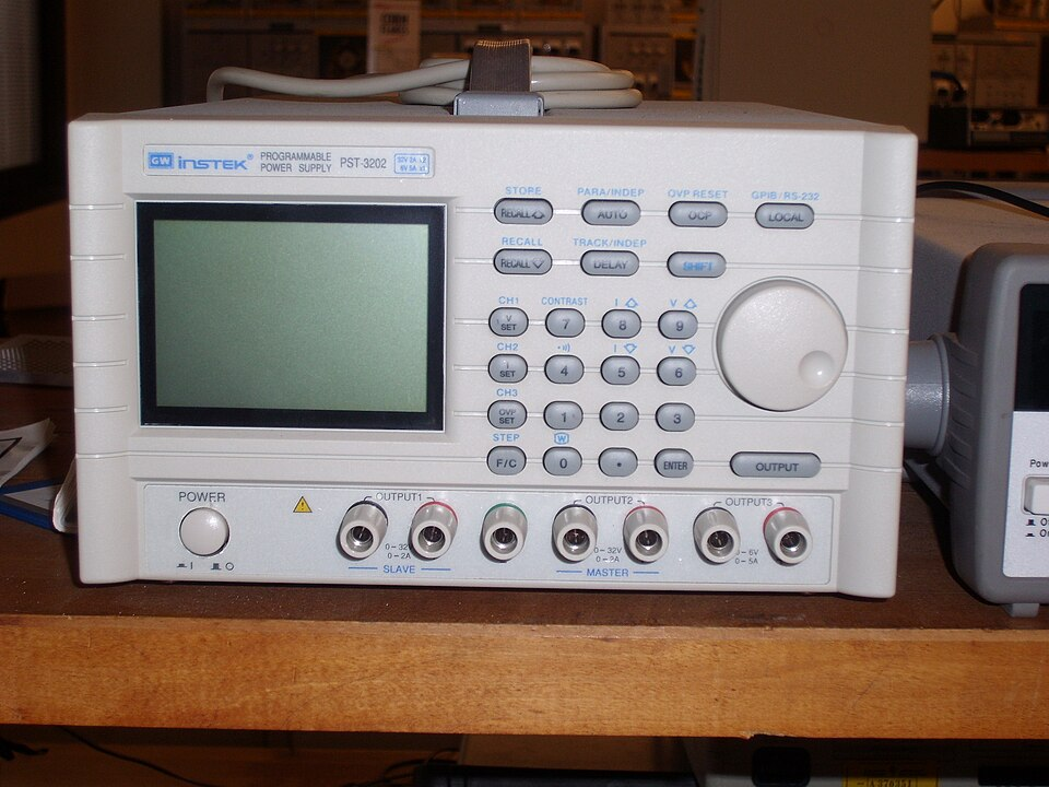
Front-panel controls and readouts on a bench DC power supply illustrate safe operation features, such as setting voltage and current limits before energising a circuit. This supports best practice for preventing overheating and accidental over-current. Source.
If a component overheats, students should immediately switch off the supply and allow the device to cool before handling.
Overheating and Component Protection
Excessive current can cause resistors, lamps, and semiconductors to heat rapidly. Overheating not only damages components but can alter their resistance, affecting measurement accuracy.
Overheating: The process by which a component’s temperature rises excessively due to power dissipation exceeding safe limits.
Preventing overheating requires attention to the power dissipation in a component.
EQUATION
—-----------------------------------------------------------------
Electrical Power (P) = I²R
P = Power dissipated in component (watts, W)
I = Current through component (amperes, A)
R = Resistance of component (ohms, Ω)
—-----------------------------------------------------------------
By selecting components with a power rating above the expected dissipation, students can safely prevent failure and maintain consistent results. Components such as thermistors and filament lamps exhibit temperature-dependent resistance, making stable temperature control essential for accurate data.
Measurement Best Practice
Accurate Voltage and Current Measurement
Accurate measurement of potential difference (V) and current (I) is fundamental when investigating resistance and I–V characteristics.
Potential Difference (V): The energy transferred per unit charge between two points in a circuit.
To obtain precise readings:
Connect voltmeters in parallel with the component under test.
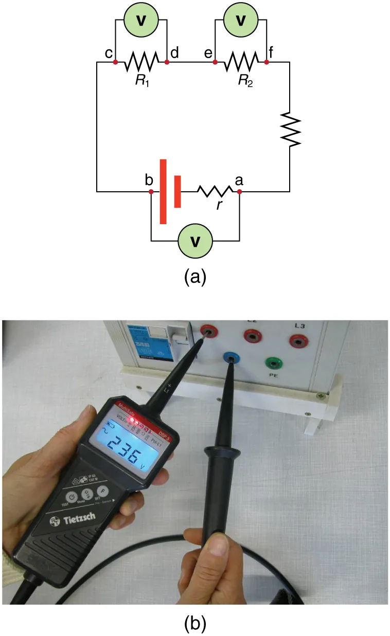
Figure 21.27 from OpenStax shows a voltmeter drawn in parallel with components in a simple series circuit, clarifying correct placement for accurate potential-difference readings. The diagram highlights that terminal voltage is measured between labelled points, aligning with standard lab technique. Extra detail included: the source’s internal resistance is shown, which supports understanding of meter-loading errors. Source.
Connect ammeters in series to measure the current through the component.
Ensure digital meters are set to the correct range to avoid overloading.
Record measurements to an appropriate number of significant figures based on instrument resolution.
Avoid touching connections while the circuit is energised.
Minimising Measurement Errors
Measurement accuracy depends not only on correct instrument use but also on careful experimental technique. Common error sources include zero offsets, meter loading, and fluctuating readings caused by unstable connections or temperature drift.
Students should:
Calibrate meters where possible.
Take multiple readings and calculate an average.
Allow components to reach a steady temperature before recording data.
Use low internal resistance ammeters and high resistance voltmeters to minimise circuit disturbance.
Note ambient temperature, as it can influence resistivity in wires and resistors.
EQUATION
—-----------------------------------------------------------------
Ohm’s Law (R) = V ÷ I
R = Resistance of component (ohms, Ω)
V = Potential difference across component (volts, V)
I = Current through component (amperes, A)
—-----------------------------------------------------------------
This relationship is only valid when temperature is constant and the material obeys ohmic behaviour. Proper measurement technique ensures that such assumptions are not violated.
Laboratory Setup and Safe Operation
Circuit Assembly Protocol
Constructing circuits from a circuit diagram requires logical order and attention to detail:
Identify each symbol and component before assembly.
Build the circuit without power applied.
Check each connection against the diagram to prevent wiring errors.
Keep lead lengths short to reduce resistance and tangling.
Label all components clearly when circuits are complex.
After assembly, a teacher or technician should inspect the setup before use if the circuit involves higher voltages or delicate semiconductors.
Practical Handling and Environment
Safety also depends on maintaining a tidy workspace and appropriate working environment.
Good laboratory habits include:
Keeping liquids away from electrical apparatus.
Wearing dry hands and insulated footwear when operating power supplies.
Using heatproof mats beneath components that may become warm.
Turning off equipment when not in use to conserve energy and reduce risk.
Risk Assessment and Reporting
Identifying and Managing Risks
Before any practical investigation, students must identify potential hazards, assess their likelihood and severity, and take preventive measures. Typical hazards in resistance experiments include electric shock, burns, and short circuits. Risk management includes:
Using low-voltage DC supplies only.
Avoiding bare wires and exposed terminals.
Never connecting mains electricity directly to experimental circuits.
Ensuring fuses and circuit breakers function correctly.
In school and laboratory settings, all circuits should operate below 24 V DC for safety.
Recording and Responding to Incidents
If a fault occurs, such as a blown fuse, smoke, or unexpected readings, the power must be switched off immediately. Students should inform a supervisor and document the issue in their practical log. Proper recording ensures both safety compliance and traceability for future improvements.
Best Practice Summary for OCR Experiments
By managing risk, avoiding overheating, and measuring voltage and current accurately, students produce valid data and protect themselves and equipment. Following these principles aligns directly with OCR’s requirement for safe, precise, and professional circuit experimentation in A-Level Physics.
Practice Questions
Question 1 (2 marks)
During an investigation into the resistance of a thermistor, a student connects a circuit to a 12 V DC power supply. Describe two safety precautions the student should take to ensure the experiment is carried out safely.
Mark Scheme
1 mark for each valid precaution, up to 2 marks total:
Ensure the circuit is switched off before altering any connections. (1)
Use a current-limiting resistor or low-voltage supply to prevent component overheating. (1)
Allow the thermistor to cool between readings if it becomes hot. (alternative valid point)
Check all wires are insulated and undamaged. (alternative valid point)
Question 2 (5 marks)
A student sets up a circuit to measure the I–V characteristics of a filament lamp. The setup includes a variable power supply, an ammeter, and a voltmeter.
(a) Explain how the student should connect the ammeter and voltmeter in the circuit to measure current and potential difference accurately. (2 marks)
(b) Describe two sources of error or risk in this experiment and explain how each can be reduced or avoided. (3 marks)
Mark Scheme
(a)
Ammeter connected in series with the lamp to measure current through it. (1)
Voltmeter connected in parallel across the lamp to measure potential difference across it. (1)
(b)
Up to 3 marks for identifying and explaining errors or risks:
Risk of overheating the filament lamp due to high current; use a current-limiting resistor or reduce voltage between readings. (1)
Inaccurate readings due to fluctuating temperature; allow lamp to cool between readings or take measurements after stabilisation. (1)
Meter inaccuracies or parallax error; ensure digital meters are zeroed and read perpendicularly to the display. (1)
FAQ
Inaccurate readings often arise from poor contact points, internal resistance of measuring instruments, or loose connections. These can create small voltage drops or unstable currents that distort measurements.
To minimise error:
Use high-quality connectors and ensure tight terminal contact.
Choose digital meters with low internal resistance (for ammeters) or high resistance (for voltmeters).
Allow components to stabilise thermally before taking readings to avoid drift caused by temperature change.
Ammeters have very low resistance, so connecting one in parallel would cause an excessive current to flow, possibly damaging the meter or circuit components.
Voltmeters, on the other hand, have very high resistance, so if connected in series, they would limit current severely, preventing the circuit from functioning properly.
Correct placement ensures safe operation and valid data collection.
Rising temperature can increase wire resistance and cause non-ohmic behaviour in components like lamps or thermistors. This can alter readings and increase power dissipation, risking overheating.
To manage this:
Take quick readings to reduce heat buildup.
Use low currents or shorter test durations.
Allow components to cool between trials.
Consistent temperature control ensures both safety and measurement reliability.
Variable supplies can easily exceed safe voltage or current limits if adjusted carelessly.
Best practice includes:
Setting voltage and current knobs to minimum before connecting the circuit.
Gradually increasing voltage while monitoring current on the display.
Ensuring the output is DC, unless an AC source is specifically required.
Keeping supply outputs below 24 V DC for school experiments.
This avoids accidental over-voltage and prevents component failure.
Environmental factors such as temperature and humidity affect resistance and contact quality in a circuit.
Recording these ensures repeatability and helps explain anomalies in data. For instance, a higher ambient temperature can cause lower current readings due to increased resistivity in metal wires.
Accurate documentation allows comparisons between trials and improves the credibility of experimental results.
