
OCR Specification focus:
‘Understand how thermistor resistance varies with temperature; identify NTC behaviour.’
Temperature Effects and Thermistors
Understanding how temperature influences electrical resistance is essential in analysing materials and their behaviour in circuits. Thermistors, particularly those with a negative temperature coefficient (NTC), are designed to demonstrate clear and predictable changes in resistance with temperature, making them vital in sensing and control systems.
The Concept of Temperature and Resistance
When a conductor or semiconductor is heated, the movement of charge carriers—such as electrons or holes—changes. This change affects how easily current can pass through the material. In metals, heating increases atomic vibrations, scattering electrons more frequently and thereby increasing resistance. In contrast, thermistors, made from semiconducting materials, behave differently because their charge carrier concentration varies strongly with temperature.
Resistance: The opposition that a material offers to the flow of electric current, measured in ohms (Ω).
In a thermistor, as the temperature rises, more charge carriers become available, allowing current to flow more easily. This results in a decrease in resistance — the defining property of an NTC thermistor.
Thermistors as Temperature-Dependent Resistors
Thermistors are resistors whose resistance changes significantly with temperature. The word derives from “thermal resistor.” The two main categories are:
NTC thermistors (Negative Temperature Coefficient): Resistance decreases as temperature increases. These are commonly used for temperature measurement, current limiting, and thermal protection.
PTC thermistors (Positive Temperature Coefficient): Resistance increases as temperature increases. These are often used in overcurrent protection circuits or as resettable fuses.
OCR focuses on NTC thermistors, as they exhibit the opposite behaviour to metallic conductors and are a practical example of semiconductor physics in action.
The Physics Behind NTC Thermistors
NTC thermistors are usually made from metal oxides such as manganese, nickel, or cobalt oxides. These materials behave as semiconductors, meaning their number of charge carriers increases exponentially with temperature.
At low temperatures, few electrons have enough energy to move into the conduction band, so resistance is high.
As temperature increases, more electrons gain thermal energy, move into the conduction band, and the number of free charge carriers rises.
The increase in charge carriers causes current to increase for a given potential difference, which means resistance decreases.
This relationship between resistance and temperature is highly non-linear, making thermistors more sensitive than metallic conductors over small temperature ranges.
Quantitative Relationship between Resistance and Temperature
The relationship between resistance RRR and temperature TTT for a thermistor can be approximated empirically by an exponential equation.
EQUATION
—-----------------------------------------------------------------
Thermistor Resistance–Temperature Relationship (R–T):
R = R₀ × e^(B(1/T – 1/T₀))
R = Resistance at temperature T (Ω)
R₀ = Resistance at reference temperature T₀ (Ω)
B = Material-specific constant (K)
T = Absolute temperature (K)
T₀ = Reference temperature (K)
—-----------------------------------------------------------------
This shows that resistance drops sharply with increasing temperature. The constant B (known as the thermistor constant) characterises how rapidly resistance changes and depends on the semiconductor composition.
Behavioural Comparison with Ohmic Conductors
Unlike an ohmic conductor such as a resistor made from copper, which obeys Ohm’s law (V proportional to I at constant temperature), a thermistor does not have a constant resistance. Its I–V characteristic is non-linear because its resistance changes dynamically with temperature.
Ohm’s Law: For a conductor at constant temperature, current (I) is directly proportional to potential difference (V), expressed as V = IR.
In an NTC thermistor, a higher current increases its temperature, reducing its resistance further and allowing even greater current flow — a positive feedback effect within limits. This property is exploited in inrush current limiters and self-regulating heaters.
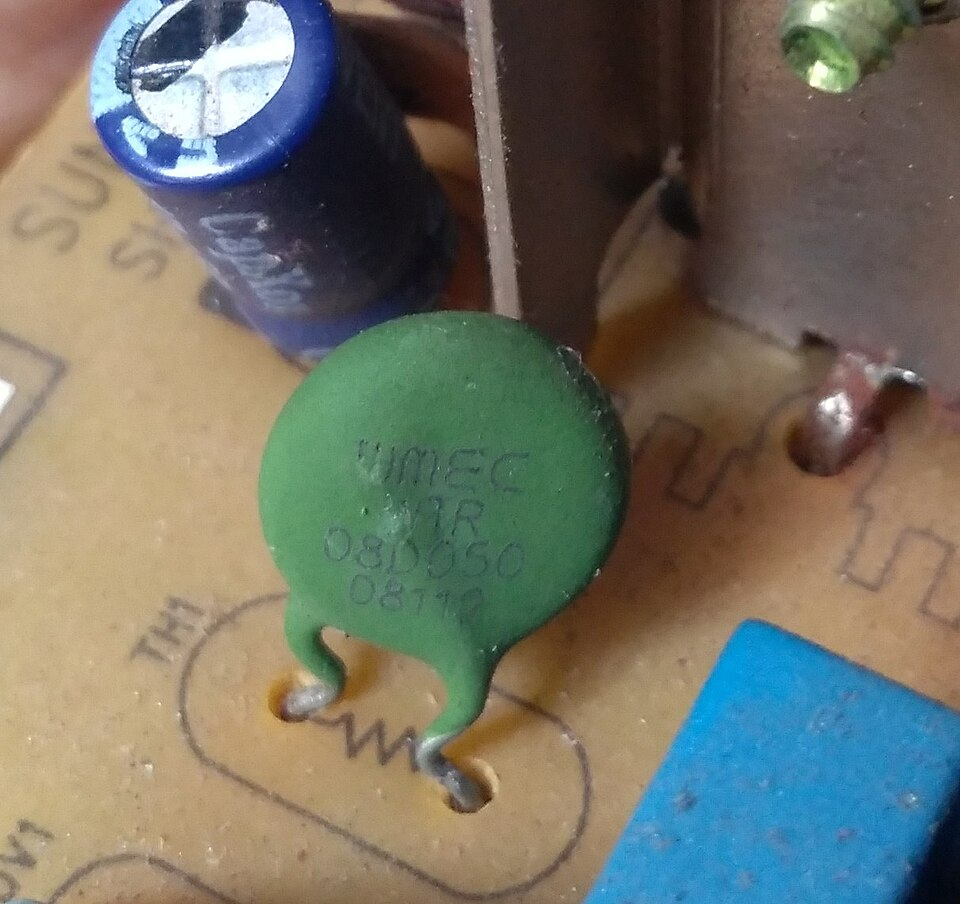
Photograph of a disc-type NTC thermistor mounted on a power-supply PCB, used here as an inrush-current limiter. While the image illustrates a power application beyond the core temperature-measurement setup, it concretely shows the device form factor students will encounter. Use alongside the schematic to connect theory to real hardware. Source.
Practical Applications of NTC Thermistors
NTC thermistors are widely used due to their predictable and repeatable response to temperature. Common uses include:
Temperature sensing: Measuring or controlling temperature in thermostats, medical devices, and digital thermometers.
Temperature compensation: Adjusting circuit performance to stabilise readings in temperature-dependent components like transistors or voltage regulators.
Inrush current limiting: Protecting power supplies or motors from surge currents by initially offering high resistance, which drops as the component warms.
Battery protection: Monitoring battery temperature during charging and discharging to prevent overheating.
Each of these applications utilises the principle that an NTC thermistor’s resistance decreases with temperature, enabling it to act as both a sensor and a control element.
Experimental Observation of Temperature Effects
In laboratory experiments, students can explore NTC behaviour by measuring resistance at different temperatures. A simple setup might include:
A thermistor connected in series with a resistor to form a potential divider.
A digital voltmeter to measure potential difference across the thermistor.
A thermometer or temperature probe to record temperature.
A water bath or controlled heat source to vary temperature.
By plotting resistance (R) against temperature (T), students observe a curve that falls steeply at lower temperatures and flattens out at higher ones. This provides visual evidence of the non-linear, exponential relationship between resistance and temperature.
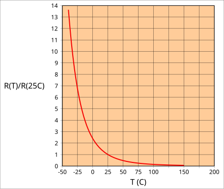
Resistance–temperature characteristic for a typical NTC thermistor. The curve demonstrates a steep drop in resistance as temperature rises, reflecting the exponential carrier-generation behaviour of semiconductor oxides. This visual underpins why thermistors are far more temperature-sensitive than metallic resistors. Source.
Material and Design Considerations
The sensitivity and accuracy of a thermistor depend on factors such as:
Material composition: Determines the B constant and resistance range.
Size and shape: Affects thermal response time — smaller thermistors respond more rapidly to temperature changes.
Encapsulation: Protects the sensing element but may slightly delay thermal response.
For high-precision applications, calibration against a standard temperature reference is essential.
Summary of NTC Behaviour
Key points for OCR Physics students to remember include:
NTC thermistors exhibit decreasing resistance with increasing temperature due to the increase in charge carrier density.
They are non-ohmic components, meaning V–I graphs are non-linear.
Their exponential R–T relationship enables use in temperature sensing and compensation.
Understanding their response is critical for accurate circuit design and analysis in both experimental and practical contexts.
Practice Questions
Question 1 (2 marks)
Explain why the resistance of a negative temperature coefficient (NTC) thermistor decreases as its temperature increases.
Mark scheme:
(1 mark) States that as temperature increases, more charge carriers (electrons) are released in the semiconductor.
(1 mark) States that the increase in charge carriers allows current to flow more easily, so resistance decreases.
Question 2 (5 marks)
A student investigates how the resistance of an NTC thermistor varies with temperature. The thermistor is placed in a beaker of water and connected in series with a resistor to form a potential divider. The student records the voltage across the thermistor at various temperatures.
(a) Explain why the thermistor’s resistance decreases with temperature in terms of the behaviour of charge carriers. (2 marks)
(b) Sketch a graph of resistance R against temperature T and describe its key features. (2 marks)
(c) State one safety precaution the student should take when carrying out this experiment. (1 mark)
Mark scheme:
(a)
(1 mark) Mentions that increasing temperature provides energy to release more charge carriers (electrons) in the semiconductor material.
(1 mark) Notes that the increased number of charge carriers lowers resistance because current can flow more easily.
(b)
(1 mark) Correctly sketches a curve showing resistance decreasing steeply at low temperatures and flattening at higher temperatures (non-linear relationship).
(1 mark) Describes that the rate of change of resistance with temperature decreases as temperature increases (curve flattens).
(c)
(1 mark) Mentions a suitable safety measure, e.g. ensuring the water bath is not overheated, avoiding electric contact with water, or using low voltage to prevent overheating of components.
FAQ
NTC thermistors are typically made from metal oxides such as manganese, nickel, cobalt, and copper oxides. These materials are semiconductors with resistivity that decreases sharply with temperature.
They are suitable because:
Their resistivity can be finely controlled through composition and sintering temperature.
They offer high sensitivity over a wide temperature range.
Their response is stable and repeatable after multiple heating and cooling cycles.
At low temperatures, a small rise in temperature produces a large increase in charge carriers, sharply lowering resistance.
At higher temperatures, most possible charge carriers are already thermally activated. Further heating releases relatively few additional carriers, so the rate of resistance decrease slows down.
This creates the distinctive exponential curve that flattens at high temperatures, indicating that the thermistor has reached a region of reduced temperature sensitivity.
An NTC thermistor is commonly connected in a potential divider circuit with a fixed resistor.
As temperature changes, the thermistor’s resistance changes.
This alters the voltage across it, producing a measurable signal related to temperature.
A microcontroller or analogue circuit can then convert this voltage into temperature using a calibration curve or equation.
This arrangement provides precise, continuous temperature readings without mechanical sensors.
NTC thermistors have several practical limitations:
Their resistance–temperature relationship is non-linear, requiring calibration or electronic compensation.
Sensitivity varies with material and geometry, limiting use across wide temperature ranges.
Self-heating due to current flow can cause measurement errors, especially in small thermistors.
They may degrade over time if exposed to high humidity or repeated extreme temperatures.
Despite these, their fast response and low cost make them highly effective in controlled environments.
When current passes through a thermistor, electrical energy is dissipated as heat within the device. This raises its temperature and further decreases its resistance — even if the surrounding temperature remains constant.
If not accounted for, this internal heating can cause inaccurate readings in sensing applications.
To minimise self-heating:
Use small measurement currents.
Allow time between readings for cooling.
Design circuits with stable, low-power biasing.
Careful management ensures reliable temperature-dependent performance.
