
OCR Specification focus:
‘For LDRs, resistance decreases as light intensity increases; use in sensing circuits.’
Light-dependent resistors (LDRs) are crucial components in electrical and electronic systems that respond to changes in light levels. Understanding their behaviour helps explain how sensors convert environmental stimuli into measurable electrical signals.
The Nature of Light-Dependent Resistors
Semiconductor foundation
An LDR (Light-Dependent Resistor) is a semiconductor device whose resistance varies with the intensity of incident light. The material used is typically cadmium sulphide (CdS) or a similar semiconductor that exhibits photoresistive behaviour.
Light-Dependent Resistor (LDR): A component whose electrical resistance decreases as the light intensity falling on it increases.
LDRs rely on the photoelectric effect, in which photons striking the material release charge carriers (electrons and holes). This process changes the number of available charge carriers and therefore alters the resistance.
Physical Principles and Electrical Behaviour
Relationship between light and resistance
The LDR’s resistance depends on how much light energy strikes its surface:
In bright light, more photons are absorbed, liberating more electrons, which increases conductivity and reduces resistance.
In dark conditions, few photons are available to excite electrons, meaning fewer charge carriers exist and resistance increases significantly.
This inverse relationship between resistance (R) and light intensity (I) is fundamental to its operation.
EQUATION
—-----------------------------------------------------------------
Resistance–Light Intensity Relationship (qualitative) = Resistance ∝ 1 / Light Intensity
R = proportional to 1 / I
R = Resistance (Ω)
I = Light intensity (lux or arbitrary units)
—-----------------------------------------------------------------
While this is not a strict linear law, it effectively describes the trend used in circuit analysis and design.
Structure and Symbolism
Physical design
An LDR is typically made of a serpentine track of semiconductor deposited on an insulating substrate, protected by a transparent layer. The shape maximises the surface area exposed to light, ensuring a strong and measurable change in resistance.
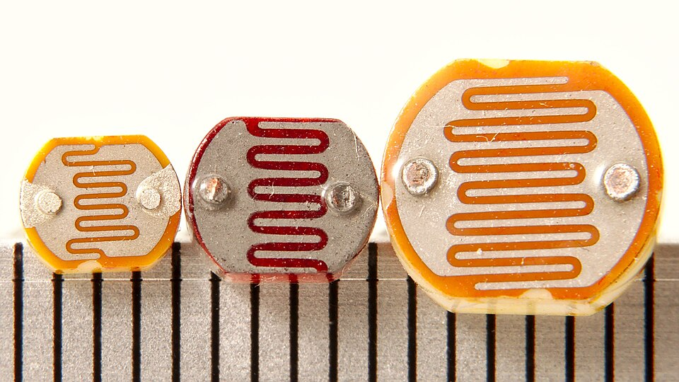
Three cadmium sulphide photoresistors of different sizes placed beside a millimetre scale. The meandering track visible on each device increases illuminated area and enhances the resistance change with light. This is a real-world counterpart to the structural description in the notes. Source.
Circuit representation
In circuit diagrams, the standard symbol for an LDR is a resistor rectangle or zigzag line with two arrows pointing towards it, representing incoming light. This symbol must be recognised and used correctly when drawing or interpreting circuit diagrams at A-Level.

Circuit symbol for a light-dependent resistor (photoresistor) showing a resistor element with two arrows indicating incident light. This aligns with the standard convention that arrows represent light falling on a photosensitive device. The symbol may be drawn using the rectangular or zigzag resistor style, depending on the convention adopted. Source.
Understanding LDR Characteristics
I–V characteristics
The current–voltage (I–V) relationship of an LDR depends on illumination:
At a fixed voltage, current increases as light intensity increases because resistance falls.
On a graph of I versus V, curves for higher light levels appear steeper, representing higher conductance.
This behaviour classifies LDRs as non-ohmic components, since their resistance is not constant but varies with external conditions.
Non-Ohmic Component: A device for which current is not directly proportional to potential difference because resistance varies with external factors such as light or temperature.
Practical Use in Sensing Circuits
Function in control systems
LDRs are widely used in sensing and control circuits to detect and respond to light levels. In such systems, the change in resistance produces a corresponding change in voltage or current, which can be measured or used to activate another component.
Typical applications include:
Automatic street lighting, where lights switch on when ambient light decreases.
Camera light meters, for exposure control.
Alarm systems, where light interruption triggers a response.
Energy management systems, such as daylight-sensitive blinds or lighting dimmers.
In each case, the LDR forms part of a potential divider or bridge circuit that converts resistance change into a usable electrical signal.
Circuit Analysis and Use of LDRs
Potential divider principle
When an LDR is connected in a potential divider circuit, its variable resistance alters the output voltage according to light level.
EQUATION
—-----------------------------------------------------------------
Potential Divider Output (Vout) = (R₂ / (R₁ + R₂)) × Vin
Vout = Output voltage (V)
R₁ = Fixed resistor (Ω)
R₂ = LDR resistance (Ω)
Vin = Supply voltage (V)
—-----------------------------------------------------------------
As light intensity increases, R₂ (the LDR) decreases, so the output voltage drops across the LDR and rises across the fixed resistor. Reversing their positions in the divider allows either an increase or decrease in voltage with increasing brightness, depending on circuit needs.
Quantitative Considerations and Response Time
Behavioural curves
An LDR’s response is typically non-linear, often following an approximate power law. This means a large resistance change occurs over a relatively small range of light intensity. The relationship can be expressed graphically, where a log-log plot of resistance versus light intensity forms a straight line, simplifying analysis in laboratory experiments.
Response time
LDRs exhibit a finite response time—a delay between a change in illumination and stabilisation of resistance. This lag, typically tens of milliseconds, arises because of recombination processes within the semiconductor. It is negligible for slow changes in ambient light but significant in fast-switching optical systems.
Material Properties and Environmental Factors
Temperature influence
Although the primary variable for LDR operation is light intensity, temperature also affects resistance, since it alters the number of thermally generated charge carriers. At higher temperatures, resistance may decrease slightly even at constant illumination, an effect that must be considered in precision measurements.
Ageing and durability
LDRs may degrade over time, particularly if exposed to prolonged intense light or high temperatures, which can cause photochemical changes in the semiconductor layer. Consequently, they are best suited for moderate-intensity, long-term monitoring applications rather than high-speed optical detection.
Summary of Functional Behaviour in Circuits
Key points for circuit interpretation
When using or analysing LDR circuits, always apply these practical insights:
Resistance decreases as light intensity increases.
Voltage across the LDR varies inversely with illumination when in a potential divider.
Non-ohmic characteristics must be accounted for when predicting circuit performance.
Correct symbol usage and circuit orientation are essential in diagrams.
LDRs are vital for automatic control systems that respond to environmental light levels.
Through these features, LDRs exemplify how physical changes in the environment are converted into measurable electrical quantities, a key principle in electronic sensing.
Practice Questions
Question 1 (2 marks)
An LDR is connected in a circuit. Explain what happens to its resistance when the light intensity falling on it increases.
Mark scheme:
1 mark: States that resistance decreases as light intensity increases.
1 mark: Explains that more charge carriers (electrons/holes) are released due to greater illumination, increasing conductivity.
Question 2 (5 marks)
A student designs an automatic night-light circuit using an LDR and a fixed resistor in a potential divider connected to a transistor and a lamp.
(a) Explain how the potential divider works as light intensity changes.
(b) Describe what happens in the circuit when darkness falls and the light turns on.
Mark scheme:
1 mark: States that the LDR’s resistance increases as light intensity decreases.
1 mark: States that as LDR resistance increases, the voltage across the LDR rises (and voltage across the fixed resistor falls).
1 mark: Explains that the potential divider output voltage changes depending on relative resistances.
1 mark: When it becomes dark, output voltage to the transistor base increases, turning it on.
1 mark: Transistor conducts, completing the circuit and allowing current to flow through the lamp, switching it on.
FAQ
LDRs are usually made from cadmium sulphide (CdS) or cadmium selenide (CdSe). These materials are chosen because their band gap energies correspond closely to the energy of visible light photons, making them highly sensitive to changes in visible illumination.
CdS responds mainly to green-yellow light, the most intense part of the solar spectrum, making it ideal for outdoor sensing applications. The material’s stability and ability to recover after illumination also make it reliable for repeated exposure.
The serpentine track increases the surface area of the photosensitive layer without increasing component size.
This layout ensures that more photons strike the material, producing a larger and more measurable change in resistance with varying light intensity.
Additionally, the zigzag shape helps distribute current evenly across the device, preventing hot spots and ensuring a consistent response throughout its surface.
LDRs are most sensitive to visible light and less responsive to infrared or ultraviolet wavelengths.
This is because the photon energy must be sufficient to excite electrons across the semiconductor’s band gap. If the wavelength is too long (infrared), photon energy is too low to create charge carriers. If it’s too short (ultraviolet), excess energy may cause unwanted heating or degradation.
Manufacturers can slightly tune sensitivity by choosing materials with different band gaps, affecting their spectral response.
Dark resistance is the resistance of the LDR when no light is incident on it.
In darkness, very few electrons are excited into the conduction band, so resistance is extremely high—often in the megaohm range.
This value is a key performance indicator for LDRs because it defines how effectively they can distinguish between bright and dark conditions in control circuits.
LDRs have relatively slow response times, often tens or hundreds of milliseconds, due to the time needed for electrons and holes to recombine after illumination changes.
For fast optical systems, such as fibre optic communications or rapid light modulation sensors, devices like photodiodes or phototransistors are preferred because they respond in microseconds.
However, the slower response of LDRs is perfectly adequate for gradual light variations in ambient sensing or automatic lighting control.
