
OCR Specification focus:
‘Measure terminal p.d. and current to determine internal resistance of a cell or supply.’
Understanding how to experimentally determine the internal resistance of an electrical power source is a key practical and theoretical skill in A-Level Physics. This topic explores how measurements of current (I) and terminal potential difference (V) reveal the internal energy losses within a source, enabling accurate modelling of real-world electrical systems through data analysis and graphical techniques.
The Concept of Internal Resistance
The Nature of Internal Resistance
A real cell or power supply is not an ideal source. When current flows, some energy is dissipated inside the source itself due to the resistance of its internal materials.
Internal resistance (r): The opposition to current flow within the power source, causing energy to be converted to heat inside the source.
Because of this, the terminal potential difference (V) — the voltage available to an external circuit — is always less than the electromotive force (E) of the source when current is flowing.
Fundamental Relationship Between E.m.f., Terminal p.d., and Current
When current flows in a circuit with internal resistance, part of the energy per coulomb is used to overcome internal opposition.
EQUATION
—-----------------------------------------------------------------
E.m.f. equation: E = V + Ir
E = electromotive force of the source (V)
V = terminal potential difference across external circuit (V)
I = current in the circuit (A)
r = internal resistance of the source (Ω)
—-----------------------------------------------------------------
This relationship forms the theoretical basis for experimental determination. Measuring V and I for different circuit loads allows both E and r to be found graphically or by calculation.
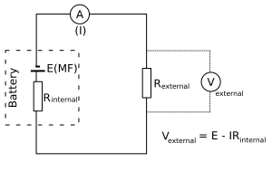
Schematic of a cell modelled as an ideal source (E) in series with internal resistance (r) supplying an external resistor. The terminal p.d. (V) is across the external circuit, while the drop (Ir) represents ‘lost volts’ inside the source. This is the circuit relationship used when plotting V against I to obtain E (intercept) and r (slope magnitude). Source.
Designing the Experiment
Essential Apparatus
To measure the internal resistance of a cell safely and accurately, the following equipment is typically required:
A cell or power supply of known approximate voltage (e.g. 1.5 V).
A variable resistor (rheostat) to control current through the circuit.
An ammeter (to measure current, ideally with low internal resistance).
A voltmeter (to measure terminal potential difference).
Connecting leads and a switch to complete the circuit.
Circuit Setup
Connect the ammeter in series with the cell and the variable resistor.
Connect the voltmeter in parallel across the cell terminals.
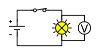
A simple series circuit with a voltmeter connected in parallel across the component under test. This mirrors how terminal p.d. is recorded while varying the external resistance to change the current. The layout is uncluttered and suitable for emphasising correct meter placement. Source.
Use the switch to control when current flows — this prevents unnecessary heating of the cell.
Vary the resistance using the rheostat to change the current, recording several V–I pairs.
Measurement Procedure
To ensure consistent and reliable data:
Close the switch briefly for each reading to prevent the cell from overheating and changing resistance.
Record current (I) and terminal potential difference (V) at several load settings.
Ensure that connections are tight to minimise contact resistance.
Take at least five readings spanning the widest practical current range.
Allow the cell to cool between measurements if noticeable heating occurs.
Each data point corresponds to a different load condition, allowing analysis of how terminal p.d. decreases as current increases.
Data Analysis and Determination of Internal Resistance
Graphical Method
The relationship between E, V, and I can be rearranged into a linear form:
EQUATION
—-----------------------------------------------------------------
Linear form: V = –rI + E
V = terminal potential difference (V)
I = current (A)
r = internal resistance (Ω)
E = electromotive force (V)
—-----------------------------------------------------------------
Plotting V (y-axis) against I (x-axis) gives a straight line with:
y-intercept = E (the e.m.f.)
gradient = –r (the negative internal resistance)
The internal resistance can then be determined from the slope’s magnitude, while the intercept gives the cell’s e.m.f. directly.
Calculating from Two Values
If only two accurate readings are available, the internal resistance may also be estimated using:
EQUATION
—-----------------------------------------------------------------
r = (E – V) / I
r = internal resistance (Ω)
E = e.m.f. (V)
V = terminal potential difference (V)
I = current (A)
—-----------------------------------------------------------------
However, this method lacks the reliability of a graph, as small measurement errors can produce large percentage uncertainties.
Experimental Considerations and Reducing Errors
Accuracy and Precision
To improve reliability and minimise uncertainty:
Use digital meters with appropriate resolution for current and voltage ranges.
Ensure constant temperature of the cell, as internal resistance increases when it warms.
Avoid parallax errors when reading analogue meters.
Keep the load resistance varied smoothly across the full current range.
Record multiple readings and calculate mean values to reduce random error.
Safety and Practical Care
Because energy is dissipated within the cell, it can overheat during repeated trials:
Do not leave the circuit closed for long periods.
Allow cooling intervals between readings.
Avoid short circuits, which can cause rapid heating and potential cell leakage or damage.
If using mains power supplies, ensure current limits are set and all connections are insulated.
Evaluating Results and Typical Sources of Error
Common Experimental Errors
Contact resistance at connections can distort measurements of small voltages.
The internal resistance of meters themselves slightly alters the true values of current and voltage.
Cells may recover partially between measurements, changing the effective internal resistance.
Fluctuations in temperature alter both external and internal resistances.
Improving Confidence in Findings
To verify accuracy:
Compare measured e.m.f. with the manufacturer’s stated value for consistency.
Plot error bars on the V–I graph to visually assess uncertainty.
Use the line of best fit to reduce the influence of anomalous readings.
Repeat the experiment with different cells to compare consistency of internal resistance values.
Linking the Experiment to Theoretical Understanding
This experiment reinforces Kirchhoff’s laws by showing that the total energy supplied by the e.m.f. equals the sum of energy dissipated externally and energy lost internally as heat. The linear relationship between V and I provides strong evidence for the model of a real source behaving as an ideal source in series with a resistor. Understanding this principle allows students to predict voltage drops and performance in practical circuits, such as batteries under heavy load or rechargeable power supplies used in laboratory equipment.
Practice Questions
Question 1 (2 marks)
Explain why the terminal potential difference of a cell is less than its electromotive force when a current flows.
Mark scheme:
1 mark for stating that energy is lost inside the cell due to its internal resistance.
1 mark for stating that some of the e.m.f. is used to overcome this internal resistance, reducing the potential difference across the external circuit.
Question 2 (5 marks)
A student investigates the internal resistance of a cell by connecting it to a variable resistor, an ammeter, and a voltmeter. Describe how the student should carry out the experiment to obtain accurate results and explain how the data can be used to determine both the electromotive force and internal resistance of the cell.
Mark scheme:
1 mark for describing the correct circuit arrangement: cell connected to a variable resistor and ammeter in series, voltmeter in parallel across the cell.
1 mark for mentioning that several pairs of current and terminal potential difference readings should be taken by varying the resistance.
1 mark for explaining that the student should close the switch only briefly for each reading to prevent the cell from overheating.
1 mark for stating that a graph of terminal potential difference (V) against current (I) should be plotted.
1 mark for identifying that the y-intercept of the graph gives the e.m.f. and the negative gradient gives the internal resistance.
FAQ
A variable resistor allows the current in the circuit to be changed smoothly without needing to alter the setup. This enables the collection of multiple current and voltage readings across a range of load conditions.
Using fixed resistors would restrict the number of measurable points and make it harder to generate a reliable V–I graph. The variable resistor therefore improves experimental efficiency and accuracy while reducing the chance of wiring errors from repeatedly changing components.
As temperature increases, the internal resistance of most cells decreases initially because ions move more freely within the electrolyte. However, excessive heating can increase resistance again due to chemical degradation or drying of materials.
Therefore, readings should be taken quickly and consistently to minimise temperature variation. This is why cells are allowed to cool between measurements to maintain consistent internal properties throughout the experiment.
When current decreases, less energy per coulomb is dissipated inside the cell as heat, meaning a smaller voltage drop occurs across the internal resistance.
Since terminal p.d. = e.m.f. – (I × r), a smaller current results in a smaller voltage loss internally, so the terminal potential difference across the external circuit rises. This relationship is central to understanding how batteries perform under varying loads.
A low-resistance voltmeter would draw additional current from the circuit, changing the true potential difference being measured.
This would cause the measured terminal p.d. to be lower than its actual value, leading to an overestimation of internal resistance. For accurate results, voltmeters are designed to have a very high resistance (ideally infinite) so that they do not significantly affect current flow in the circuit.
Yes, but only with careful control and appropriate current limiting. A high-voltage supply can replace a cell if:
It has an adjustable output to keep currents small.
Current-limiting or protective resistors are included in the circuit.
Proper insulation and safety procedures are followed.
For educational contexts, it is preferable to use low-voltage DC supplies or chemical cells to reduce risk and ensure that internal heating and electrical hazards remain minimal.
