
OCR Specification focus:
‘A source has an e.m.f. and internal resistance causing energy losses within the source.’
Electrical energy sources such as cells and power supplies provide energy to circuits, but not all of that energy reaches the external components. Some energy is inevitably lost within the source itself due to its internal resistance. Understanding how electromotive force (e.m.f.) and internal resistance interact is essential to analysing real electrical systems and predicting their performance accurately.
The Nature of an Electromotive Force (e.m.f.)
Every electrical energy source is designed to convert another form of energy into electrical energy, such as chemical, mechanical, or electromagnetic energy. The electromotive force (e.m.f.) represents the total energy supplied per unit charge by the source to move charge around the circuit, including through its own internal structure.
Electromotive force (e.m.f.): The energy transferred per coulomb of charge from chemical or other forms into electrical energy within a source.
E.m.f. is measured in volts (V) and symbolised by E. Although the term includes “force,” it actually refers to a potential difference that drives current around a circuit.
Energy Conversion in a Source
Inside a typical electrochemical cell, chemical reactions move charges, creating a potential difference between the terminals. This process transfers energy to charge carriers (usually electrons) that flow through the external circuit. However, as current flows, the materials inside the source oppose this flow due to their finite resistivity.
This opposition gives rise to internal resistance, which causes some of the electrical energy generated by the e.m.f. to be dissipated as heat inside the source.
Understanding Internal Resistance
Internal resistance (r) is the resistance within the source itself — in wires, electrolytes, electrodes, and other internal components. It limits the current the source can supply and affects the terminal potential difference (terminal p.d.) observed across the external circuit.
Internal resistance: The resistance within an electrical power source that causes energy losses as current passes through the source’s internal materials.
Origin of Internal Resistance
In chemical cells, it arises from resistance of the electrolyte and contact resistance at electrodes.
In generators, it comes from resistance of windings and frictional effects.
In batteries or power supplies, heating of components also increases internal resistance over time or with use.
As a result, no real source is ideal; all have measurable internal resistance, though high-quality sources are designed to minimise it.
Relationship Between e.m.f., Terminal p.d., and Internal Resistance
The internal resistance reduces the useful voltage available to the external circuit. When current flows, a voltage drop occurs within the source, meaning the external terminals show a smaller potential difference than the e.m.f.
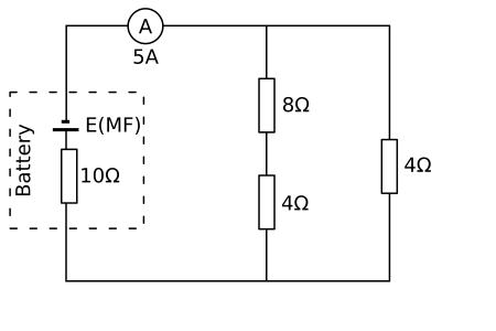
Schematic of a real source represented by an ideal e.m.f. (E) in series with an internal resistance (r), supplying a load (R). The internal resistor accounts for energy dissipated inside the source, so the terminal p.d. is less than the e.m.f. when current flows. Labels are minimal and clear, matching A-Level circuit conventions. Source.
EQUATION
—-----------------------------------------------------------------
Equation Name: Relationship between e.m.f., terminal p.d., and internal resistance
E = V + Ir
E = electromotive force (V)
V = terminal potential difference (V)
I = current through the circuit (A)
r = internal resistance of the source (Ω)
—-----------------------------------------------------------------
This equation shows that the total energy per coulomb supplied by the source (E) equals the energy per coulomb delivered to the external circuit (V) plus the energy per coulomb lost internally as heat (Ir).
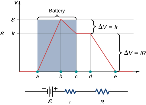
Graph of electric potential around a battery–resistor loop. The rise of ε across the source is followed by an internal drop of I r, leaving the terminal p.d. V = ε − I r across the external load. This visual highlights lost volts inside the source; the full loop plot includes extra context beyond the core definition. Source.
Behaviour Under Different Loads
When no current flows (I = 0): No internal voltage drop occurs, so V = E. The terminal p.d. equals the e.m.f.
When current increases: The internal voltage drop Ir increases, reducing terminal p.d.
When short-circuited (V = 0): All the e.m.f. is lost across the internal resistance, giving a maximum current I = E/r.
This dependence explains why a battery’s voltage often drops under heavy load conditions or as it discharges.
Energy Distribution and Efficiency
Energy conservation dictates that the total electrical energy produced by the e.m.f. is shared between the useful energy in the external circuit and the energy dissipated inside the source.
Useful output power: Puseful=VIP_{useful} = VIPuseful=VI
Power lost internally: Ploss=I2rP_{loss} = I^2rPloss=I2r
Total power supplied: Ptotal=EIP_{total} = EIPtotal=EI
Efficiency can therefore be defined as the ratio of useful output power to total supplied power:
η=VE=RR+r\eta = \frac{V}{E} = \frac{R}{R + r}η=EV=R+rR
where R is the external resistance.
A higher external resistance results in greater efficiency, as a larger proportion of the energy appears across the external load.
Modelling Real and Ideal Sources
Ideal Source
An ideal source is a theoretical concept that assumes zero internal resistance. In such a case:
All the e.m.f. appears as terminal p.d.
No energy is wasted inside the source.
The source can deliver any current without voltage drop.
Real Source
In practice, all cells and power supplies are non-ideal, exhibiting measurable internal resistance. This means:
Terminal voltage decreases with increasing current.
Power is lost internally, reducing efficiency.
The current a source can deliver safely is limited by its internal resistance and heating effects.
Manufacturers sometimes specify a nominal internal resistance so that users can estimate expected voltage drops under different load conditions.
Practical Implications of Internal Resistance
Internal resistance affects circuit performance in several important ways:
It limits the maximum current available from the source.
It causes voltage sag when powering high-current devices.
It determines how a battery behaves when connected to various loads.
It impacts the accuracy of experimental measurements if not accounted for.
Reducing Internal Resistance
Using materials with low resistivity for electrodes and conductors.
Designing cells with larger surface areas to lower current density.
Operating within optimal temperature ranges to reduce resistive heating.
Connecting cells in parallel to reduce effective internal resistance and maintain voltage.
Each of these design strategies aims to minimise energy losses, improving overall system efficiency and stability.
Internal Resistance and Real-World Performance
In high-current applications such as electric vehicles or power tools, internal resistance plays a critical role. A small increase in internal resistance can lead to significant power loss and heating, reducing battery lifespan and safety. In precision electronics or sensing circuits, internal resistance affects voltage regulation and measurement accuracy, so it must be carefully considered during circuit design.
By recognising the interplay between e.m.f., internal resistance, and terminal p.d., physicists and engineers can more accurately predict how electrical sources behave under real operating conditions — an essential skill for advanced circuit analysis and reliable system design.
Practice Questions
Question 1 (2 marks)
Define the term electromotive force (e.m.f.) and explain how it differs from the terminal potential difference (p.d.) of a cell when current is flowing.
Mark Scheme:
1 mark: States that e.m.f. is the energy supplied per coulomb of charge by the source.
1 mark: Explains that terminal p.d. is less than the e.m.f. when current flows because energy is lost across the internal resistance of the cell.
Question 2 (5 marks)
A cell of e.m.f. 6.0 V and internal resistance 0.5 Ω is connected to a variable resistor.
(a) Derive an expression for the terminal potential difference of the cell in terms of the current I. (2 marks)
(b) The current is measured as 2.0 A. Calculate the terminal potential difference. (1 mark)
(c) Explain what would happen to the terminal potential difference if the current were increased further, and give a reason for your answer. (2 marks)
Mark Scheme:
(a)
1 mark: States or uses the relationship E = V + Ir.
1 mark: Rearranges correctly to give V = E – Ir.
(b)
1 mark: Substitutes correctly: V = 6.0 – (2.0 × 0.5) = 5.0 V.
(c)
1 mark: States that terminal p.d. decreases as current increases.
1 mark: Explains that a larger current causes a greater voltage drop (Ir) across the internal resistance, leaving less voltage available across the external circuit.
FAQ
Internal resistance increases as a cell ages due to chemical and physical degradation. Electrolyte concentration may decrease, electrode surfaces may corrode, and internal connections can weaken, all of which increase resistivity.
Temperature also affects resistance:
Higher temperatures temporarily lower internal resistance as ions move more freely.
Lower temperatures increase resistance as ionic mobility decreases.
Repeated charging and discharging in rechargeable cells cause material fatigue and buildup of reaction by-products, which further raise internal resistance over time.
When the circuit is opened, current stops flowing and no energy is dissipated through the internal resistance. The voltage drop across internal resistance (Ir) becomes zero, so the terminal voltage rises to equal the full e.m.f.
This “recovery” happens because chemical or ionic gradients within the cell stabilise once current ceases, restoring the full potential difference between the terminals.
To determine internal resistance:
Connect the cell to a variable resistor (rheostat) and an ammeter–voltmeter setup.
Record terminal voltage (V) and current (I) for several load values.
Plot a graph of V against I.
The gradient of the graph gives –r, and the y-intercept gives E, the e.m.f. of the cell.
Accurate results require:
Avoiding short circuits.
Allowing the cell to cool between readings.
Using instruments with low internal resistance.
High-current devices such as electric motors or power tools draw large currents. Even a small internal resistance causes a significant voltage drop (Ir) and considerable energy loss as heat.
This can lead to:
Reduced performance and efficiency.
Overheating, shortening the battery’s lifespan.
Voltage instability affecting sensitive components.
For this reason, such devices use cells with very low internal resistance, often lithium-based or with advanced electrode designs.
‘Lost volts’ refers to the potential difference across the internal resistance of a source — the portion of e.m.f. not available to the external circuit.
Lost volts = Ir, so they depend on the current drawn.
When current increases, lost volts increase, lowering terminal voltage.
When current decreases, lost volts reduce, so terminal voltage rises.
Over prolonged use, lost volts can fluctuate as internal resistance changes with temperature and cell condition.
