
OCR Specification focus:
‘Avoid short circuits; allow cells to cool; justify measuring techniques and uncertainties.’
Practical experiments involving sources of e.m.f. and internal resistance require careful planning to ensure both accurate results and safe working conditions. This section explores the essential safety precautions, measurement considerations, and methods to minimise uncertainty when determining internal resistance in electrical circuits.
Experimental Safety and Risk Management
Avoiding Short Circuits
A short circuit occurs when a low-resistance path allows a large current to flow directly across a source, potentially causing damage or overheating.
To prevent short circuits:
Ensure all connections are secure and made with appropriate resistance.
Avoid connecting a cell or power supply directly across an ammeter or wire without a load resistor.
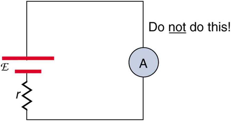
Incorrect meter placement can create a near-short across the source, allowing excessive current through a low-resistance ammeter path. This risks meter damage and rapid heating of leads. Extra detail: internal resistance rrr is shown to emphasise that even with rrr, the current can still be dangerously large. Source.
Check circuit diagrams before powering the circuit to confirm all resistive components are in place.
Use low-voltage sources (typically less than 12 V) in laboratory setups.
Employ fuses or current-limiting resistors where large current surges could occur.
A short circuit may cause wires to heat rapidly, which risks burns, equipment damage, or battery leakage. Recognising early signs such as unexpected heat or the smell of burning insulation is vital for immediate circuit disconnection.
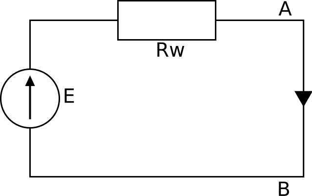
Short-circuit condition for a cell with emf EEE and internal resistance rrr; the load path is bypassed so current is limited only by rrr. This explains dangerously high currents and rapid heating. The Polish annotations in the summary are nonessential; the diagram itself is universal and uncluttered. Source.
Thermal Considerations and Cooling Procedures
Allowing Cells to Cool
Repeated current flow through cells leads to internal heating, primarily due to the internal resistance (r) of the source. This heating can:
Alter the electromotive force (e.m.f.) temporarily.
Change resistance values, affecting precision.
Risk thermal degradation of the cell materials.
Good laboratory practice includes:
Limiting the duration of current flow to short intervals.
Allowing cooling periods between readings when measuring terminal potential difference at varying currents.
Avoiding continuously running variable resistors or potentiometers at high currents.
Monitoring the temperature of the cell helps identify thermal effects that could introduce systematic error. If a cell becomes warm to the touch, readings should be paused until it returns to ambient temperature.
Measurement Techniques and Minimising Uncertainty
Accurate Data Collection
Precise measurements of terminal potential difference (V) and current (I) are central to determining internal resistance.
To improve reliability:
Use digital multimeters with suitable resolution (e.g., ±0.01 V, ±0.01 A).
Take multiple readings across a wide current range.
Record both increasing and decreasing current sequences to identify hysteresis effects.
Instrument Placement and Calibration
Correct circuit setup ensures valid data:
Connect the voltmeter across the cell terminals to measure terminal p.d., not across other components.
Insert the ammeter in series with minimal internal resistance to reduce voltage loss.
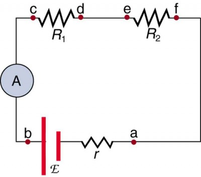
Ammeter in series and voltmeter across a component ensure safe, meaningful measurements of current and terminal p.d. The diagram also shows a source with emf EEE and internal resistance rrr, reinforcing the model used when determining internal resistance. Extra detail: two series resistors R1R_1R1 and R2R_2R2 appear as generic loads, which is acceptable and need not be emphasised. Source.
Check instruments for zero errors before measurement.
Calibrate equipment if available, comparing with known references.
Instrumental uncertainty should always be expressed with each reading, typically as ±(smallest division or manufacturer’s tolerance).
Understanding and Managing Uncertainties
Sources of Uncertainty
Uncertainties arise from both instrumental and methodological factors:
Resolution limits of voltmeters and ammeters.
Temperature fluctuations altering resistance.
Contact resistance at connection points.
Timing inaccuracies if measurements are taken too quickly after circuit adjustments.
When determining internal resistance graphically (e.g., from a V–I graph), the gradient and intercept carry uncertainties propagated from these factors. This affects the derived values of r and E (e.m.f.).
Improving Precision
To reduce uncertainty:
Keep leads short and connections clean.
Repeat readings and compute mean values.
Plot best-fit lines using many data points to reduce random error influence.
Clearly record ambient conditions (temperature, equipment used) for reproducibility.
Equipment and Procedural Justifications
Choosing Appropriate Components
When analysing circuits involving internal resistance:
Select load resistors that allow a safe but measurable current (e.g., 0.1–1 A).
Avoid low-resistance bulbs or components that cause high current draw.
Prefer rechargeable cells in repeated trials to maintain consistent e.m.f.
Practical Setup Considerations
Before conducting measurements:
Inspect wires for fraying or exposed metal.
Ensure power supplies are set to the correct voltage range.
Disconnect the circuit immediately if unexpected readings or heating occur.
Good experimental design requires balancing measurable current flow with safety limits. Using variable resistors allows for controlled current adjustments without reconfiguring the circuit.
Data Validity and Experimental Reliability
Controlling Environmental Variables
Environmental factors can subtly influence outcomes:
Temperature alters resistivity of wires and internal resistance.
Humidity can affect contact surfaces.
Ambient electromagnetic noise may induce small measurement fluctuations.
Maintain stable laboratory conditions, ensuring repeatable and comparable results.
Consistency in Measurement Technique
Consistency reduces systematic error. Always:
Use the same instruments throughout an experiment.
Read scales at eye level to avoid parallax.
Start measurements from zero current and gradually increase to desired levels.
Evaluating and Reporting Experimental Quality
Justifying Techniques
An essential component of OCR practical assessment involves explaining why specific techniques are used. Justifications include:
Using short measurement intervals to limit heating.
Applying ohmic components to maintain proportional relationships.
Taking three or more readings for each variable to enhance statistical confidence.
Students should be able to articulate how these strategies minimise error and enhance safety.
Reporting Uncertainty
Uncertainties should be expressed clearly with measured quantities. Example:
V = 1.50 ± 0.01 V, I = 0.35 ± 0.01 A.
This allows later calculation of percentage uncertainty and assessment of experimental precision.
Summary of Best Practices for Practical Safety
Always inspect circuits before connection.
Avoid short circuits and uncontrolled current flow.
Allow cells to cool between readings to prevent damage.
Record uncertainties and justify each measurement approach.
Work within safe voltage and current limits appropriate to the lab environment.
Adhering to these safety and measurement principles ensures accurate, reliable, and safe determination of internal resistance in accordance with OCR A-Level Physics standards.
Practice Questions
Question 1 (2 marks)
Explain why it is important to avoid creating a short circuit when investigating the internal resistance of a cell in a laboratory experiment.
Mark scheme:
1 mark for recognising that a short circuit causes a large current to flow due to very low resistance in the circuit.
1 mark for noting that this can cause overheating, damage to the cell or equipment, or pose a safety hazard such as burns or fire risk.
Question 2 (5 marks)
A student designs an experiment to determine the internal resistance of a cell by measuring the terminal potential difference (p.d.) and current for different load resistances.
Discuss the practical considerations and safety precautions the student should take to ensure reliable and safe results.
Mark scheme:
Award up to 5 marks:
1 mark for stating that currents should be kept low to avoid heating effects and reduce error.
1 mark for mentioning that cells should be allowed to cool between readings to maintain constant internal resistance.
1 mark for suggesting that short measurement periods should be used to prevent the cell from warming.
1 mark for describing how to avoid short circuits (e.g. never connect the cell directly across an ammeter or wire).
1 mark for noting that instrument calibration and uncertainty recording are required to ensure accuracy and reliability.
FAQ
If the cell warms up, its internal resistance increases due to temperature-dependent changes in the materials inside. This means the measured terminal potential difference for a given current may decrease over time, leading to inconsistent or misleading results.
To maintain accuracy:
Take readings quickly and allow cooling periods.
Keep ambient conditions stable.
Record temperature changes if noticeable, to discuss potential systematic errors.
High currents cause greater power loss within the cell (P = I²r). This not only wastes energy but also leads to significant heating, which changes the internal resistance during the experiment.
Additionally, the cell’s chemical reactions can become non-linear at high discharge rates, making Ohm’s law less applicable. Keeping current below about 1 A ensures readings remain within the cell’s normal operating range.
Contact resistance arises at junctions between wires, terminals, and clips. It adds extra, unwanted resistance to the circuit, which can falsely increase the apparent internal resistance value.
To minimise contact resistance:
Clean terminals and connectors before use.
Use crocodile clips rather than loose wires.
Avoid repeatedly moving connections between readings.
Record uncertainties alongside each measurement of voltage and current. For digital instruments, this is usually the smallest displayed unit (e.g., ±0.01 V).
Combine these when analysing data:
Use percentage uncertainty = (uncertainty ÷ reading) × 100%.
Apply uncertainty rules when calculating values of e.m.f. and internal resistance from graphs.
Include uncertainty ranges on plotted data points where appropriate.
OCR requires students to demonstrate understanding of method validity. Justifying each technique shows that results are not obtained blindly but with awareness of their physical and experimental basis.
Examples include:
Explaining why using a digital multimeter improves precision.
Justifying cooling intervals as a way to stabilise internal conditions.
Clarifying that measuring several load resistances helps to identify a consistent V–I relationship.
